
If you live in an older house, you may know this problem. You want to hang something on the wall or ceiling, start to drill a hole and suddenly the drill starts to wander. You end up with a pretty big hole in the wall that is way too big for the screws you want to use. In this project we want to design a special wall anchor that can help you in this case.
We will create our first extrusion object using the 2D basic shapes square and circle together with the linear extrusion transformation linear_extrude. Furthermore, we will get to know a new variant of the rotation transformation rotate as well as the 3D basic shape cylinder. Lastly, we will deepen our knowledge of already known functions.
Again, let’s start by first defining a module and a test instance of that module:
// a special wall anchor with lots of adjustments
// (all sizes in millimeter)

module wall_anchor (
    drill_hole_dm,          // drill hole diameter
    screw_dm,               // screw diameter
    length                  // anchor length
){

}

wall_anchor(8,5,50);
Since we are going to add quite a few parameters to our module, we arrange the parameters as a vertical list this time. This also allows us to add comments to the parameters right next to them. Let’s begin with a square shaped wall anchor. We will add the round version of the anchor as an option later. If the wall anchor has a square cross-section and it has to fit into a round drill hole, then the diagonal of the square must correspond to the diameter of the drill hole. In order to derive the side length of the square from the diameter of the drill hole, old Pythagoras can help us again:
/* ... */
module wall_anchor (
    drill_hole_dm,          // drill hole diameter
    screw_dm,               // screw diameter
    length                  // anchor length
){

    side_length = sqrt( pow(drill_hole_dm, 2) / 2 );

    linear_extrude( height = length )
    square( side_length, center = true );

}
/* ... */
We know that a^2 + b^2 = c^2 holds true in a right triangle. In our particular case here, the long side of the triangle c is given and we are looking for the length of the small sides. Since our triangle is in a square, we already know that the small sides are equal in length. So we can rewrite our formula to a^2 + a^2 = c^2 or 2 x a^2 = c^2. If we now move the 2 to the other side of the equation, we are almost done: a^2 = c^2 / 2. To get a, we only have to take the square root: a = sqrt( c^2 / 2 ).
In this project we do not use the 3D basic shape cube to describe the body of the wall anchor. Instead, we use its two-dimensional counterpart square and then transform the 2D shape into a 3D object by using linear_extrude. We will see the benefit of this approach in the next step.
As mentioned above, our wall anchor should also work in “difficult” drill holes that have become larger than planned due to the drill wandering. Therefore, we want the basic shape of our anchor to be wedge-shaped. We add two new parameters that will allow us to adjust our wall anchor in this regard as needed. The parameter oversize will be added to the drill diameter. The parameter outer_taper is a taper factor that makes the wall anchor thinner towards the end. Instead of a factor one could also consider specifying a “target diameter”. However, this would mean that you always have to specify this diameter, since it has to be selected to match the borehole diameter. Using a taper factor allows to give the parameter a reasonable default value that links the resulting taper to the borehole diameter. Thus, the parameter has to be changed only if this default value does not lead to a good result. As we implement the taper in our geometry description we can now benefit from our decision to use a combination of square and linear_extrude instead of using a cube:
/* ... */
module wall_anchor (
    drill_hole_dm,          // drill hole diameter
    screw_dm,               // screw diameter
    length,                 // anchor length
    oversize        = 2,    // outer diameter oversize
    outer_taper     = 0.75, // outer taper factor
){

    outer_dm    = drill_hole_dm + oversize;
    side_length = sqrt( pow(outer_dm, 2) / 2 );

    linear_extrude( height = length, scale = outer_taper )
    square( side_length, center = true );

}
/* ... */
The transformation linear_extrude offers a parameter scale, with which we can reduce or enlarge the 2D shape along the extrusion path. So with the help of this parameter we can very easily describe the desired taper of the wall anchor. The parameter oversize is used in the calculation of side_length.
The cavity inside our wall anchor, i.e., the hole in which we screw in the screw, has the shape of a funnel. At the beginning, the hole in the anchor has the diameter of the screw. Then it tapers so that the screw can push the sides of the anchor apart and press them against the inside of the hole. We can make this funnel shape with two cylinders and subtract both from our main body using a Boolean difference operation:
/* ... */
module wall_anchor (
    drill_hole_dm,          // drill hole diameter
    screw_dm,               // screw diameter
    length,                 // anchor length
    oversize        = 2,    // outer diameter oversize
    outer_taper     = 0.75, // outer taper factor
    inner_taper     = 0.2,  // inner taper factor
    inner_taper_end = 0.3,  // relative end of inner taper along length
){

    difference() {

        outer_dm    = drill_hole_dm + oversize;
        side_length = sqrt( pow(outer_dm, 2) / 2 );

        linear_extrude( height = length, scale = outer_taper )
        square( side_length, center = true );

        // hole
        abs_taper_end = length * inner_taper_end;
        taper_dm      = screw_dm * inner_taper;

        translate( [0, 0, -0.01] )
        union() {
            $fn = 24;

            cylinder( d1 = screw_dm, d2 = taper_dm, h = abs_taper_end + 0.01);

            translate( [0, 0, abs_taper_end] )
            cylinder( d = taper_dm, h = length - abs_taper_end + 0.02 );
        }

    }

}
/* ... */
We have added two more parameters to our module. The parameter inner_taper sets the taper factor of the inner diameter and determines how thin the neck of our funnel shape becomes. The parameter inner_taper_end sets the position where the neck of our funnel shape starts. The position is specified relative to the length of the anchor. Inside the module, we made the definition of our wall anchor shape the first element of a Boolean difference operation. We then described our funnel shape as the second element of this operation in order to subtract it from the main body. For this we first derive the absolute values abs_taper_end and taper_dm from the relative parameters inner_taper_end and inner_taper. We then describe the funnel shape with two cylinders. The first cylinder uses a new form of parameterization. Instead of a diameter d we specify two diameters d1 and d2. This creates a blunt cone with diameter d1 at the bottom and diameter d2 at the top. In our case we start with the screw diameter screw_dm and end with the diameter of the taper taper_dm. The height corresponds to the end of the taper abs_taper_end plus some allowance. The second cylinder is defined with just one diameter and describes the neck of our funnel shape. It has the diameter taper_dm and as height the remaining length of the anchor (length - abs_taper_end) plus some allowance. We combine both cylinders with a Boolean union and move the funnel shape minimally down so that the difference operation with the anchor main body performs cleanly.
A small side note: within the Boolean union, the first statement sets the special variable $fn, which we use to control the level of detail of our geometry. Since we want to increase the level of detail of both cylinders, we can simply set the variable $fn within the local geometry set of the Boolean operation. By doing so, we will affect all curved geometries inside the set.
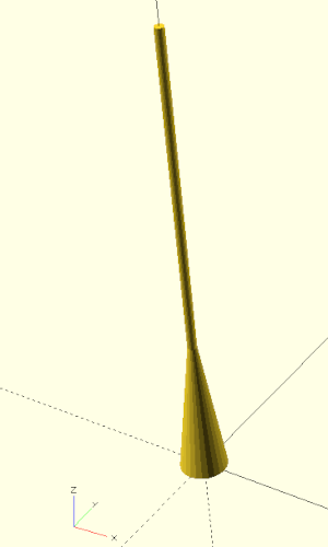
! characterSince our funnel shape is the subtractive part of a difference operation, it is somewhat difficult to model the shape “blindly”. If we prefix the funnel shape with an exclamation mark (!translate( ... ) union() ...) and run a preview, then only the funnel shape will be drawn and no other geometry (Figure 4.). This selective preview of individual geometry parts is very useful and you will probably use it very often as a modeling aid.
Our wall anchor is still missing the ability to expand when a screw is screwed in. To allow for such expansion, we slit the anchor on all four sides using cubes and the Boolean difference operation:
/* ... */
module wall_anchor (
drill_hole_dm, // drill hole diameter
screw_dm, // screw diameter
length, // anchor length
oversize = 2, // outer diameter oversize
outer_taper = 0.75, // outer taper factor
inner_taper = 0.2, // inner taper factor
inner_taper_end = 0.3, // relative end of inner taper along length
collar = 0.1, // relative length of initial non-slit part
slit = 0.5, // slit width
cap_size = 2, // length of the end cap
){
difference() {
outer_dm = drill_hole_dm + oversize;
side_length = sqrt( pow(outer_dm, 2) / 2 );
/* .. */
// slits
abs_collar = length * collar;
for (i = [0:1])
rotate( [0, 0, i * 90] )
translate([
-(side_length + 2) / 2,
-slit / 2,
abs_collar
])
cube ([
side_length + 2,
slit,
length - cap_size - abs_collar
]);
}
}
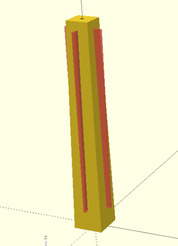
/* ... */We have added three more parameters to our model to control the slits in the wall anchor. The parameter collar defines how long the section should be at the beginning of the anchor where there are no slits. This length is given relative to the total length. The parameter slit defines the thickness of the slits in millimeters. The parameter cap_size determines how many millimeters before the end of the anchor the slits should end. Preventing the slits to go through the end of the wall anchor stabilizes the anchor. Within the module description, the slits are modeled using a box (cube). The box is translated such that it is centered above the origin of the X/Y plane at a Z-level of abs_collar and then rotated around the Z-axis. The rotation is parameterized by the loop variable i, which runs from 0 to 1. Thus, we create 2 instances of the box: one rotated by 0 degrees and one rotated by 90 degrees. To check the shape of these two boxes, you can make them temporarily visible by prefixing the for-loop with a # character and running a preview (Figure {}}).
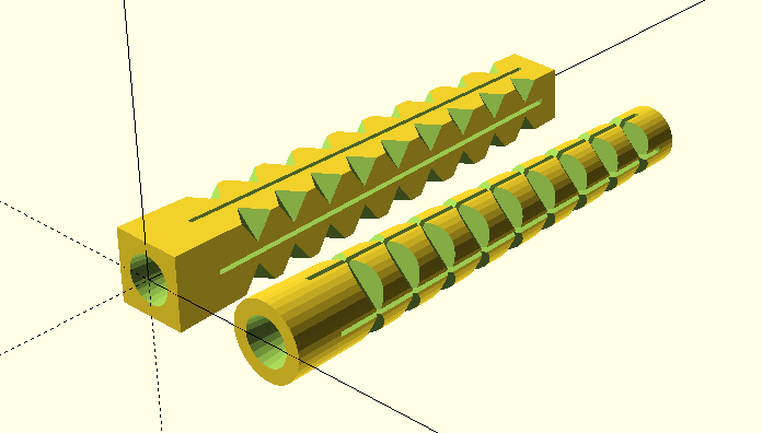
# characterIn order to be able to grip well in a drilled hole, we now want to give our wall anchor some teeth:
/* ... */
module wall_anchor (
    drill_hole_dm,          // drill hole diameter
    screw_dm,               // screw diameter
    length,                 // anchor length
    oversize        = 2,    // outer diameter oversize
    outer_taper     = 0.75, // outer taper factor
    inner_taper     = 0.2,  // inner taper factor
    inner_taper_end = 0.3,  // relative end of inner taper along length
    collar          = 0.1,  // relative length of initial non-slit part
    slit            = 0.5,  // slit width
    cap_size        = 2,    // length of the end cap
    teeth_div       = 5,    // divisor determining the number of teeth
    teeth_depth     = 1.5,  // depth of the teeth
){

    difference() {

        outer_dm    = drill_hole_dm + oversize;
        side_length = sqrt( pow(outer_dm, 2) / 2 );

        /* .. */

        abs_collar = length * collar;

        /* .. */

        // teeth
        teeth_count = floor( (length - abs_collar) / teeth_div );
        teeth_dist  = (length - abs_collar) / (teeth_count + 1);

        opposite   = (outer_dm - (outer_dm * outer_taper)) / 2;
        hypotenuse = sqrt( pow(opposite, 2) + pow(length, 2) );
        angle      = asin( opposite / hypotenuse );

        diag_dist = sqrt( pow(outer_dm/2 - teeth_depth, 2) / 2 );

        for ( j = [0:90:359] )
        rotate( [0, 0, j] )
        rotate( -angle, [1,1,0] )
        for (i = [1:teeth_count] )
        translate( [diag_dist, -diag_dist, abs_collar + i * teeth_dist] )
        rotate([0,0,-45])
        translate( [0, -outer_dm / 2, 0] )
        rotate([0,45,0])
        cube( outer_dm );

    }

}
/* ... */
For the teeth we define two more parameters. The parameter teeth_div determines the number of teeth relative to the length of the wall anchor. The parameter teeth_depth defines how deep the teeth should penetrate into the main body of the anchor. Inside the module we first derive the absolute values teeth_count and teeth_dist from the parameter teeth_div. The length considered for the number of teeth is the length of the anchor minus the collar. The function floor used here rounds the value passed to it down to the nearest integer. The value teeth_dist is used to distribute the teeth evenly along the anchor. The number of teeth is increased by 1 in this context to gain some distance from the edge at both the beginning and the end of the anchor. Since our anchor tapers, we also need to determine the angle of the side edge using the arc sine. Lastly, we need the distance diag_dist, which gives us the displacement in X- and Y-direction that is needed to translate from the origin to the outer tip of the wall anchor base.
After these preparations, we can now describe the teeth geometry. Since our geometry description contains a whole series of steps, it is advisable to preview each step by placing a ! sign in front of the geometry description at corresponding positions. We start with a cube that has an edge length of outer_dm. If we put the ! sign directly in front of cube and run a preview (F5), only this cube will be displayed. In the next step we rotate the cube by 45 degrees along the Y-axis (!rotate( [0, 45, 0] )). This creates the “cutting face” along the Y-axis, which we will use later to cut into the base body. Now we center the cube over the X-axis by moving it half its length along the Y-axis (!translate( [0, -outer_dm / 2, 0] )). Now the cube is in a good position to be rotated around the Z-axis by -45 degrees (!rotate([0,0,-45])). The cube is almost in the right position. We only have to move it to the outer edge of the anchor base and a little bit upwards (!translate( [diag_dist, -diag_dist, collar_abs + i * teeth_dist] )). In this translate transformation we have already included the loop variable i. If we now put a for loop in front of it, we end up with a tower of cubes (!for ( i = [1:teeth_count] )).
We need to take care of the taper of our wall anchor now. Our cube tower should be tilted in such a way that it follows the side of the wall anchor’s edge. For this we have to rotate the cube tower by angle degrees. However, we don’t want to rotate around any of the coordinate axes, but around an axis that lies exactly between the X- and Y-axis. To achieve this we use a special form of the rotate transform. This special form receives the rotation angle as first parameter and the rotation axis as second parameter (!rotate( -angle, [1,1,0])).
We’re almost there! Now we only have to copy our tilted cube tower three times, rotating it 90 degrees each time. We do this with another for-loop and a corresponding rotate transformation (!for ( j = [0:90:359]) rotate( [0, 0, j] )). The for-loop ends at 359 and not at 360, because otherwise we would have cube towers at 0 degrees and at 360 degrees lying on top of each other.
As a final touch, we want to give our special wall anchor the option of having a round base shape instead of a square one:
module wall_anchor (
    drill_hole_dm,          // drill hole diameter
    screw_dm,               // screw diameter
    length,                 // anchor length
    oversize        = 2,    // outer diameter oversize
    outer_taper     = 0.75, // outer taper factor
    inner_taper     = 0.2,  // inner taper factor
    inner_taper_end = 0.3,  // relative end of inner taper along length
    collar          = 0.1,  // relative length of initial non-slit part
    slit            = 0.5,  // slit width
    cap_size        = 2,    // length of the end cap
    teeth_div       = 5,    // divisor determining the number of teeth
    teeth_depth     = 1.5,  // depth of the teeth
    round_shape     = false // make the anchor round instead of square
){

    difference() {

        outer_dm = drill_hole_dm + oversize;
        side_length   =
            round_shape ? outer_dm : sqrt( pow(outer_dm, 2) / 2 );

        linear_extrude( height = length, scale = outer_taper )
        if ( round_shape )
            circle( d = side_length, $fn=36 );
        else
            square( side_length, center = true );

        // hole
        abs_taper_end = length * inner_taper_end;
        taper_dm      = screw_dm * inner_taper;

        translate( [0, 0, -0.01] )
        union() {
            $fn = 24;

            cylinder( d1 = screw_dm, d2 = taper_dm, h = abs_taper_end + 0.01);

            translate( [0, 0, abs_taper_end] )
            cylinder( d = taper_dm, h = length - abs_taper_end + 0.02 );
        }


        // slits
        abs_collar = length * collar;

        for (i = [0:1])
        rotate( [0, 0, i * 90] )
        translate([
            -(side_length + 2) / 2,
            -slit / 2,
            abs_collar
        ])
        cube ([
            side_length + 2,
            slit,
            length - cap_size - abs_collar
        ]);

        // teeth
        teeth_count = floor( (length - abs_collar) / teeth_div );
        teeth_dist  = (length - abs_collar) / (teeth_count + 1);

        opposite = (outer_dm - (outer_dm * outer_taper)) / 2;
        hypotenuse  = sqrt( pow(opposite, 2) + pow(length, 2) );
        angle = asin( opposite / hypotenuse );

        diag_dist = sqrt( pow(outer_dm/2 - teeth_depth, 2) / 2 );

        for ( j = [0:90:359] )
        rotate( [0, 0, j] )
        rotate( -angle, [1,1,0] )
        for (i = [1:teeth_count] )
        translate( [diag_dist, -diag_dist, abs_collar + i * teeth_dist] )
        rotate([0,0,-45])
        translate( [0, -outer_dm / 2, 0] )
        rotate([0,45,0])
        cube( outer_dm );

    }

}

wall_anchor(8,5,50);
The option to make the anchor round or square is controlled by the newly added parameter round_shape. Inside the geometry description we have extended two code locations with a case distinction. First, the side_length is set depending on the parameter round_shape. Second, we distinguish between circular and square basic shape by means of an if-branch. Note that here the if-branch itself is treated like a geometry that is then extruded by a linear_extrude transform.
Our finished wall anchor module has received quite a lot of parameters! However, by defining most of the parameters as relative parameters and giving them sensible default values, the module remains pretty usable. Only the three parameters drill_hole_dm, screw_dm and length have to be specified. Everything else adapts automatically in relation to these three parameters.
After you have rendered the geometry (F6) and exported it as a .stl file (F7), you can load the .stl file into the slicer software of your 3D printer. Here, you have to decide if you want to print the anchor standing up or lying down. Lying down should make the anchor a bit more stable and it will require less printing time, but it will also require a support structure that you have to remove after printing. If you print the anchor upright, the need for a support structure is eliminated. In this case, you might want to reduce the printing speed a bit so that the individual layers have more time to cool down sufficiently before the next layer is applied. In addition, it could be advantageous to print with a so-called brim so that the contact area of the anchor on the print bed is increased and print bed adhesion is improved.