
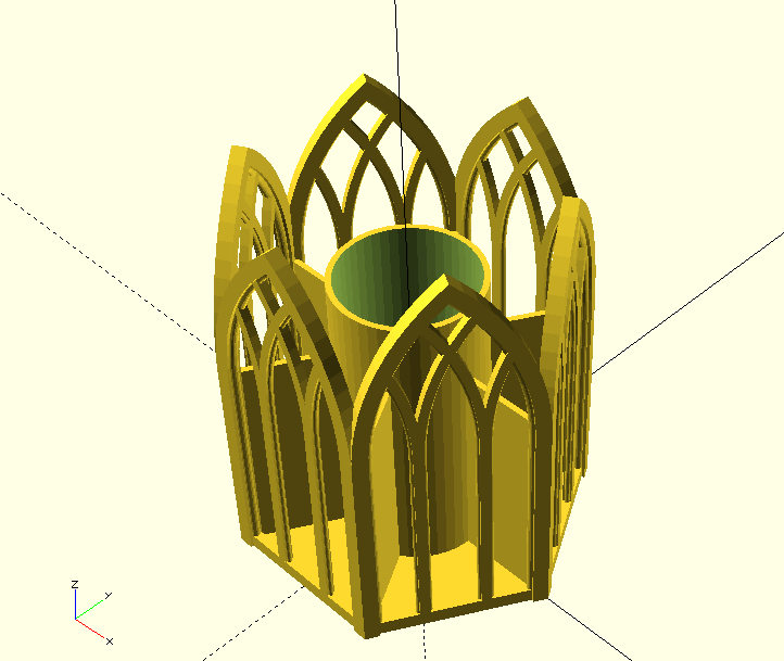
In this project, we want to construct a pen holder that has plenty of space for our desk utensils and can be 3D printed without support structure. The design will be inspired by gothic architecture.
We learn about the rotate extrusion transform. In addition, we use an exploratory design approach this time that develops the final module “from the inside out”.
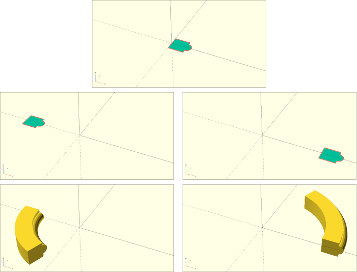
Core element of the pen holder are gothic-looking arches on the outside. To create these arches, the rotate extrusion transform is a good choice. Similar to the linear extrusion, rotate_extrude acts on a 2D geometry and creates a 3D object from it. Unlike linear_extrude, however, the 2D geometry is not extruded along a straight line but along an (implicit) curve.
The rotate_extrude transformation takes some time to get used to as some of its properties are implicitly given by the position of the 2D geometry that is being extruded. Approximately, rotate_extrude operates the following way: first, the given 2D geometry is set upright by rotating it around the X-axis. Then the geometry is extruded by rotating it clockwise around the Z-axis. Thus, the resulting 3D geometry depends a lot on where the 2D geometry was located initially (Figure 7.).
Let’s start our arch with a 2D geometry consisting of a square and a circle:
arch_base   = 5;
arch_angle  = 70;
arch_radius = 20;

rotate( [-90, 0, 0])
rotate_extrude( angle = arch_angle, $fn = 100 )
translate( [-arch_radius, 0] )
union(){
    translate( [0, -arch_base / 2] )
    square( arch_base );

    translate( [arch_base, 0] )
    circle( d = arch_base * 3 / 5, $fn = 18);
}
We create a square with side length arch_base and move it to the center of the X-axis. Since we are in two dimensions, our translate transformation requires only a two-dimensional vector as input. Additionally, we define a circle, which has a diameter of 3/5 of the square size and position the circle at the outer edge of the square. We connect the square and the circle to a joint 2D geometry using a Boolean union.
Now we can set the radius of our arch by moving the 2D geometry along the X axis away from the origin. Since we want the circle of our geometry to be on the inside of the arch, we move our geometry in the negative X-direction (translate( [-arch_radius, 0] )). Only after this translation we can apply the rotate_extrude transform to create our arch piece. The parameter angle specifies how far the 2D geometry should be rotationally extruded. An angle of 360 degrees would result in a closed ring. In older versions of OpenSCAD, no angle could be specified and a closed ring was always generated. After the rotational extrusion, the arch piece lies on its side. With a rotation around the X-axis we can finally set the arc upright.
To create the opposite side of the arch, we can simply use a combination of for-loop and mirror transformation:
arch_base   = 5;
arch_angle  = 70;
arch_radius = 20;

for (m = [0:1])
mirror( [m, 0, 0] )
rotate( [-90, 0, 0])
rotate_extrude( angle = arch_angle, $fn = 100 )
translate( [-arch_radius, 0] )
union(){
    translate( [0, -arch_base / 2] )
    square( arch_base );

    translate( [arch_base, 0] )
    circle( d = arch_base * 3 / 5, $fn = 18);
}
The loop variable m takes the value 0 and the value 1 exactly once and thus creates a normal and a mirrored version of our arch piece. However, there is now a gap between our arches that we still need to close. The problem is that our original arch piece does not directly touch the Z axis with its top edge at the end of the arch. This creates a gap when we mirror it. So we have to move our arch piece to touch the Z-axis before mirroring:
arch_base   = 5;
arch_angle  = 70;
arch_radius = 20;

for (m = [0:1])
mirror( [m, 0, 0] )
translate( [cos(arch_angle) * arch_radius, 0, 0] )
rotate( [-90, 0, 0])
rotate_extrude( angle = arch_angle, $fn = 100 )
translate( [-arch_radius, 0] )
union(){
    translate( [0, -arch_base / 2] )
    square( arch_base );

    translate( [arch_base, 0] )
    circle( d = arch_base * 3 / 5, $fn = 18);
}
It turns out that the distance to the Z-axis can be described by cos(arch_angle) * arch_radius. This is not obvious at first. It helps to sketch the situation on a piece of paper to identify the “suitable” right triangle and then use the cosine… (cos(a) = adjacent / hypotenuse).
If we now play a little with the parameters arch_radius and arch_angle, we see that the two halves of the arc always meet neatly. For further use of our arch, the previous parameterization is a bit uncomfortable. Ideally, we would prefer to specify the width of the complete arch from outer edge to outer edge and calculate the radius to match. This can be done in the following way:
arch_width  = 50;
arch_base   = 5;
arch_angle  = 70;
arch_radius = arch_width / (2 - 2 * cos(arch_angle) );

for (m = [0:1])
mirror( [m, 0, 0] )
translate( [cos(arch_angle) * arch_radius, 0, 0] )
rotate( [-90, 0, 0])
rotate_extrude( angle = arch_angle, $fn = 100 )
translate( [-arch_radius, 0] )
union(){
    translate( [0, -arch_base / 2] )
    square( arch_base );

    translate( [arch_base, 0] )
    circle( d = arch_base * 3 / 5, $fn = 18);
}
In this case, too, it is helpful to sketch out the whole thing and set up an equation that establishes a relationship between arch_angle, arch_radius and arch_width. You can then transform this equation so that arch_radius is singled out on one side of the equal sign.
The last thing missing are two vertical columns below our arch. We can describe them with the same basic shape and a linear extrusion. Lastly, we can now package the whole thing into a module:
module arch(
    arch_width,
    arch_base,
    arch_angle,
    pillar_height
) {

    arch_radius = arch_width / (2 - 2 * cos(arch_angle) );

    module basic_shape() {
        union(){
            translate( [0, -arch_base / 2] )
            square( arch_base );

            translate( [arch_base, 0] )
            circle( d = arch_base * 3 / 5, $fn = 18);
        }
    }

    translate( [0, 0, pillar_height] )
    for (m = [0:1])
    mirror( [m, 0, 0] )
    translate( [cos(arch_angle) * arch_radius, 0, 0] )
    union(){
        rotate( [-90, 0, 0])
        rotate_extrude( angle = arch_angle, $fn = 100 )
        translate( [-arch_radius, 0] )
        basic_shape();

        translate( [0, 0, -pillar_height] )
        linear_extrude( height = pillar_height )
        translate( [-arch_radius, 0] )
        basic_shape();
    }
}

arch(
    arch_width    = 50,
    arch_base     = 5,
    arch_angle    = 75,
    pillar_height = 50
);
We have made the variables arch_width, arch_base and arch_angle parameters of the new module arch and added a new parameter pillar_height. Inside the module we encapsulated our 2D base shape into a submodule because we need the base shape in two places - for the arch and for the pillars. At the point where we set our original arch piece upright by rotating it around the X-axis, we split the geometry description of the arch and inserted a Boolean union. This way, we can add a pillar below the arch, that will then be shifted and mirrored in tandem with the arch.
There is still one flaw in our geometry description. If we use small angles, e.g. 30 degrees, then the tips of the mirrored arch parts “break through” each other. To prevent this, we need to trim the tips. We can do this with a Boolean difference operation, which we place just before the mirror transform:
/* ... */
    translate( [0, 0, pillar_height] )
    for (m = [0:1])
    mirror( [m, 0, 0] )
    difference(){
        translate( [cos(arch_angle) * arch_radius, 0, 0] )
        union(){
            rotate( [-90, 0, 0])
            rotate_extrude( angle = arch_angle, $fn = 100 )
            translate( [-arch_radius, 0] )
            basic_shape();

            translate( [0, 0, -pillar_height] )
            linear_extrude( height = pillar_height )
            translate( [-arch_radius, 0] )
            basic_shape();
        }

        translate([
            0,
            -arch_base,
            sin(arch_angle) * arch_radius - 5 * arch_base
        ])
        cube( 5 * arch_base);
    }

/* ... */
Now we can use our module arch to define one side of our pen holder. To do this, we instantiate the module several times with adjusted parameters in each case and position the individual parts relative to each other in a suitable way:
arch_width    = 60;
arch_base     = 5;
arch_angle    = 50;
pillar_height = 75;

// main arch
arch(
    arch_width,
    arch_base,
    arch_angle,
    pillar_height
);

width_factor = 2 / 3;
base_factor  = 3 / 5;

// inner arches
displacement_x1 =
    (arch_width -
     arch_width * width_factor -
     arch_base / 2) / 2;

for(v = [-1:2:1])
translate( [displacement_x1*v, 0, 0] )
arch(
    arch_width * width_factor,
    arch_base * base_factor,
    arch_angle * 0.82,
    pillar_height
);

// inner side arches
displacement_x2 =
    (arch_width -
     arch_width * (1 - width_factor) -
     arch_base / 2) / 2;

for(v = [-1:2:1])
translate( [displacement_x2*v, 0, 0] )
arch(
    arch_width * (1 - width_factor),
    arch_base * base_factor,
    arch_angle * 0.58,
    pillar_height
);
The resulting geometry description is not very complicated, but a bit confusing. If you are confronted with such a description and want to get an overview of which part of the geometry description corresponds to which component in the output window, the highlighting of individual parts by means of a preceding # character is very helpful. As with the description of a single arch, we use for-loops to create local copies of the geometry where needed. In this case, the subsequent geometry description is not mirrored, but translated once in the negative and once in the positive direction along the X-axis. This is achieved by the loop variable taking on the values -1 and 1. To prevent the loop variable from becoming 0 on its way from -1 to 1 we set the step size to 2.
Now we can encapsulate our single side into a module and let the module arch become a submodule of this new module:
module side_piece(
    arch_width,
    arch_base,
    arch_angle,
    pillar_height
) {

    module arch(
        arch_width,
        arch_base,
        arch_angle,
        pillar_height
    ) {

        /* ... */

    }

    // main arch

    /* ... */

    // inner arches

    /* ... */

    // inner side arches

    /* ... */
}

arch_width    = 60;
arch_base     = 5;
arch_angle    = 50;
pillar_height = 75;

side_piece(
    arch_width,
    arch_base,
    arch_angle,
    pillar_height
);
Although the module side_piece and its submodule arch now have parameters with the same name, there is no confusion (at least not on the side of OpenSCAD). The respective “inner” variables cover the “outer” ones. So in the module arch the parameter arch_width of the module side_piece is no longer visible. Only the parameter arch_width of the module arch can be accessed.
Now we can use the side_piece module to describe our pen holder. Let’s start with a hexagonal arrangement:
arch_width    = 60;
arch_base     = 5;
arch_angle    = 50;
pillar_height = 75;

hexagonal_height = arch_width / ( 2 * tan(30) );

for (r = [0:60:359])
rotate( [0, 0, r] )
translate( [0, hexagonal_height - arch_base / 2, 0] )
side_piece(
    arch_width,
    arch_base,
    arch_angle,
    pillar_height
);
To create a hexagon, we need to move the side piece a specific distance along the Y-axis and then rotate (and copy) it 5 times by 60 degrees around the Z-axis. To determine this specific distance we have to calculate the distance of the hexagon sides to the center of the hexagon. Again, it helps to sketch out the elements in question on a piece of paper. The perpendicular line from the center of the hexagon to the center of a hexagon side has an angle of 30 degrees to the radius of the hexagon. The radius is the hypotenuse in the resulting triangle. The central, perpendicular line is the adjacent and half of the hexagon side is the opposite. As the tangent of an angle is equal to the adjacent divided by the opposite (and we are interested in the adjacent), opposite / tan(30) gives us the length we are looking for. Since the opposite is half of the hexagon side that has length arch_width, we finally end up with the formula (arch_width / 2) / tan(30), which in turn can also be written as arch_width / (2 * tan(30) ).
Since we have constructed the side pieces centered on the X-axis, we need to translate them by arch_base / 2 less than just calculated. Next we describe the base of the pen holder and its border:
arch_width    = 60;
arch_base     = 5;
arch_angle    = 50;
pillar_height = 75;

bottom_thickness = 1;
border_height    = 5;
border_thickness = 3;

hexagonal_height = arch_width / ( 2 * tan(30) );

for (r = [0:60:359])
rotate( [0, 0, r] )
translate( [0, hexagonal_height - arch_base / 2, 0] )
union() {
    side_piece(
        arch_width,
        arch_base,
        arch_angle,
        pillar_height
    );

    // bottom plate
    translate( [-arch_width / 2, -hexagonal_height, 0] )
    cube( [arch_width, hexagonal_height, bottom_thickness] );

    // border
    translate( [-arch_width / 2, -border_thickness / 2, 0] )
    cube( [arch_width, border_thickness, border_height] );
}
We simply take advantage of the symmetry of the hexagon and describe only one part of the bottom panel and one part of the border at a time, and then use a Boolean union to align and rotate these parts together with the side piece.
Finally, we take care of the inner geometry of the pen holder. It consists of a hollow cylinder and six inner walls:
/* ... */

cylinder_dm     = 50;
cylinder_height = 100;
cylinder_walls  = 2;

hexagonal_height = arch_width / ( 2 * tan(30) );
hexagonal_radius = arch_width / ( 2 * sin(30) );

/* ... */

// center cylinder
difference() {
    cylinder( d = cylinder_dm, h = cylinder_height ,$fn = 50);

    translate( [0, 0, bottom_thickness] )
    cylinder(
        d = cylinder_dm - 2 * cylinder_walls,
        h = cylinder_height ,
        $fn = 50
    );
}

// inner walls
for (r = [0:60:359])
rotate( [0, 0, r] )
translate( [cylinder_dm/2 - 0.1, -cylinder_walls / 2, 0] )
cube([
    hexagonal_radius - cylinder_dm/2 - arch_base / 2,
    cylinder_walls,
    pillar_height
]);
We create the hollow cylinder in the center by means of a Boolean difference operation, where we subtract a second, smaller and upward shifted cylinder. For the inner walls we now need the radius of the hexagon. You can derive the radius using the same reasoning as before. Only that one does not use the tangent here but the sine. The inner walls consist of a rectangle, which is first shifted appropriately and then rotated (and copied) five times by 60 degrees.
The overhangs in our pen holder are kept small enough such that you should be able to print the holder without a support structure. Printing becomes more challenging the larger we choose arch_angle. If you have problems printing the overhangs, try reducing the layer height in your slicer program. Alternatively or additionally, you can try to increase the line width. With a typical 0.4 millimeter nozzle you should be able to print line widths of 0.5 to 0.6 millimeters without any problems. Last but not least, you can also try to reduce the printing speed. In that case the blower at the print nozzle has more time to cool down the freshly printed plastic.