
In this project we will model a stamp whose geometry automatically adjusts to the size of the text with which the stamp is parameterized.
We will work with the 2D basic shape text and see that a certain limitation of OpenSCAD makes our life particularly hard when using text. We will work around this limitation in a tricky way and the Boolean operation intersection as well as the projection transform will help us with that. Furthermore we will get to know the offset, minkowski and scale transformations and test out how to operate OpenSCAD from the command line.
Let’s start by defining a basic structure for our model description. We define a module stamp and two submodules relief and stamp_body. We split the stamp geometry into two submodules as we may want to 3D print the stamp relief and the stamp body separately, e.g. to be able to use different printing materials:
module stamp (
    txt,                       // stamp text
    font_size,                 // approx. height of letter
    font         = "Liberation Sans:style=Bold Italic",
    stamp_depth  = 2,          // depth of the stamp relief
){

    module relief() {
        // text
        linear_extrude( height = stamp_depth )
        text(
            text = txt,
            size = font_size,
            font = font,
            valign = "center",
            halign = "center",
            $fn = 50
        );
    }

    module stamp_body() {

    }

    color("Peru")
    relief();

    stamp_body();

}

stamp("OpenSCAD",10);
Our module stamp has four parameters for now. The parameter txt sets the text of the stamp, the parameter font_size sets the (maximum) height of a regular capital letter in millimeters and the parameter font sets the font to be used. An overview of the fonts available in OpenSCAD can be found in the menu under Help -> Font List. The fourth parameter stamp_depth defines the depth of the stamp relief.
In the relief submodule we use the 2D base shape text to generate a two-dimensional geometry of the stamp text. We set the vertical and horizontal alignment of the font (valign and halign) to center and pass txt, font size and font type as further parameters. As with circles, spheres or cylinders, we can specify the level of detail of the geometry with the special variable $fn. We can use the resulting text geometry like any other 2D basic shape. In this case we extrude (linear_extrude) the text to the desired depth of the stamp relief.
To continue in our model description, it would be useful if we could get the width and height of the text. The height will be similar to the font size. The width depends on the particular txt. It may be surprising, but there is no way in OpenSCAD to find out these dimensions! This limitation of OpenSCAD makes it very difficult to define geometries that automatically adapt to a given text. We’re going to try it anyway, and we have to dig deep into our bag of tricks to do it. We start by defining another submodule text_area and create the text inside of it again as a 2D base shape and extrude it to 3 millimeters:
module stamp (
    /* ... */
){

    module text_area() {
        linear_extrude( height = 3)
        text(
            text = txt,
            size = font_size,
            font = font,
            valign = "center",
            halign = "center",
            $fn = 50
        );
    }

    !text_area(); // debug

    /* ... */

}
/* ... */
It is advisable to instantiate the text_area submodule once under the module definition and prefix the instance with a ! character. This way you can better follow the step-by-step construction of the text_area module. Now things get tricky. We set our text upright by rotating it 90 degrees around the X-axis. Then we use the projection transform to project the standing text onto the X-Y plane and connect the projected “shadows” of each letter using the hull transformation:
module stamp (
    /* ... */
){

    module text_area() {
        hull()
        projection()
        rotate([90,0,0])
        linear_extrude( height = 3)
        text(
            text = txt,
            size = font_size,
            font = font,
            valign = "center",
            halign = "center",
            $fn = 50
        );
    }

    !text_area(); // debug

    /* ... */

}
/* ... */
It is a good idea to follow the described steps individually by means of preview (F5) or render (F6) (Figure {{imginc>}}{{imgref>}}). If you use render instead of preview, the 2D shapes will be better recognizable as such.
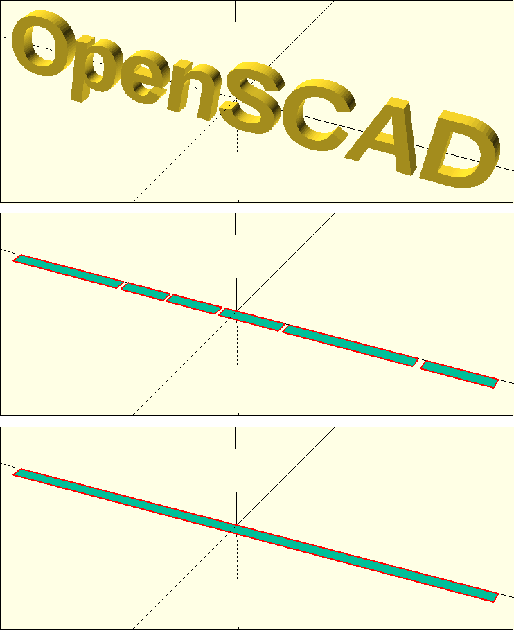
We have made some progress in determining the text area. We now have a 2D shape that has the width of our text. Let’s just apply the trick again, only now we don’t rotate around the X-axis, but around the Y-axis:
module stamp (
    /* ... */
){

    module text_area() {
        hull()
        projection()
        rotate([90,0,0])
        linear_extrude( height = 3)
        text(
            text = txt,
            size = font_size,
            font = font,
            valign = "center",
            halign = "center",
            $fn = 50
        );

        hull()
        projection()
        rotate( [0, 90, 0] )
        linear_extrude( height = 1 )
        text(
            text = txt,
            size = font_size,
            font = font,
            valign = "center",
            halign = "center",
            $fn = 50
        );
    }

    !text_area(); // debug

    /* ... */

}
/* ... */
Now we have another 2D shape representing the height of our text. Note that this time we have only extruded by one millimeter. What we’re missing now is a way to combine these two 2D shapes. If we extrude each of the shapes by a suitable length and then superimpose them, the intersection of these two shapes should have exactly the geometry we are looking for. For the “suitable length” of the first shape, we need to estimate what the maximum height of the text will be. Here we can simply assume ‘3 x font size’. For the length we can take the number of characters in the text, multiply this by the font size and then use a safety factor of two. With these values we can now extrude the 2D shapes and let them overlap using rotate and translate transforms:
module stamp (
    /* ... */
){

    module text_area() {

        estimated_length = len(txt) * font_size * 2;

        translate( [0,0,-1] )
        rotate([-90,0,0])
        translate([0,0,-(3 * font_size) / 2])
        linear_extrude( height = 3 * font_size )
        hull()
        projection()
        rotate([90,0,0])
        linear_extrude( height = 3)
        text(
            text = txt,
            size = font_size,
            font = font,
            valign = "center",
            halign = "center",
            $fn = 50
        );

        rotate( [0, -90, 0] )
        translate( [0, 0, -estimated_length/2] )
        linear_extrude( height = estimated_length )
        hull()
        projection()
        rotate( [0, 90, 0] )
        linear_extrude( height = 1 )
        text(
            text = txt,
            size = font_size,
            font = font,
            valign = "center",
            halign = "center",
            $fn = 50
        );
    }

    !text_area(); // debug

    /* ... */

}
/* ... */
Note the use of the len function to get the number of characters of the stamp text. In the same way, the len function also allows to get the number of elements in an array. We are almost there! We can now use the Boolean operation intersection to create the intersection of our two 3D shapes and then apply another projection transform to convert it back to a 2D shape:
module stamp (
    /* ... */
){

    module text_area() {

        estimated_length = len(txt) * font_size * 2;

        projection()
        intersection(){
            translate( [0,0,-1] )
            rotate([-90,0,0])
            translate([0,0,-(3 * font_size) / 2])
            linear_extrude( height = 3 * font_size )
            hull()
            projection()
            rotate([90,0,0])
            linear_extrude( height = 3)
            text(
                text = txt,
                size = font_size,
                font = font,
                valign = "center",
                halign = "center",
                $fn = 50
            );

            rotate( [0, -90, 0] )
            translate( [0, 0, -estimated_length/2] )
            linear_extrude( height = estimated_length )
            hull()
            projection()
            rotate( [0, 90, 0] )
            linear_extrude( height = 1 )
            text(
                text = txt,
                size = font_size,
                font = font,
                valign = "center",
                halign = "center",
                $fn = 50
            );
        }
    }

    !text_area(); // debug

    /* ... */

}
/* ... */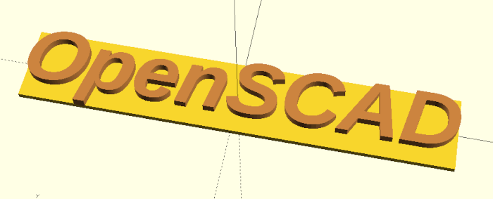
If you now remove the ! character again and run a preview (F5) you can see that we have reached our goal (Figure 8.). We have created a 2D surface that can automatically adjust to the size of the stamp text! We will now use this special surface to construct the rest of the stamp. Before we continue, we should make sure that we remove our “debug” instance of the text_area now.
Let us return to the relief submodule and use our text_area module to describe the relief background:
module stamp (
    txt,                       // stamp text
    font_size,                 // approx. height of letter
    font         = "Liberation Sans:style=Bold Italic",
    stamp_depth  = 2,          // depth of the stamp relief
    stamp_margin = 5,          // margin of the text

    stamp_relief_depth = 2,    // depth of the relief substrate
){

    /* ... */

    module relief() {
        // text
        linear_extrude( height = stamp_depth )
        text(
            text = txt,
            size = font_size,
            font = font,
            valign = "center",
            halign = "center",
            $fn = 50
        );

        // relief base
        translate( [0, 0, stamp_depth] )
        linear_extrude( height = stamp_relief_depth )
        offset( delta = stamp_margin )
        text_area();
    }

    /* ... */
}
/* ... */
We extend our module stamp with the parameters stamp_margin and stamp_relief_depth, which define the margin around the text and the depth of the relief background. We model the relief background based on the text_area and extend it with the transformation offset. This transformation expands the subsequent 2D geometry by the parameter delta or shrinks the geometry if delta is negative. Then we extrude our expanded text_area to stamp_relief_depth and position it above the stamp text using a translate transformation (translate( [0, 0, stamp depth] )).
It would be nice if we could optionally add a border to our stamp text. We can construct such a border based on our text_area as well:
module stamp (
    txt,                       // stamp text
    font_size,                 // approx. height of letter
    font         = "Liberation Sans:style=Bold Italic",
    stamp_depth  = 2,          // depth of the stamp relief
    stamp_margin = 5,          // margin of the text

    stamp_relief_depth = 2,    // depth of the relief substrate

    border           = true,   // enable text border
    border_thickness = 2,      // text border thickness
    border_radius    = 2,      // text border radius
){

    /* ... */

    module relief() {
        // text
        linear_extrude( height = stamp_depth )
        text(
            text = txt,
            size = font_size,
            font = font,
            valign = "center",
            halign = "center",
            $fn = 50
        );

        // relief base
        translate( [0, 0, stamp_depth] )
        linear_extrude( height = stamp_relief_depth)
        offset(delta = stamp_margin + (border ? border_thickness : 0))
        text_area();

        // border
        if (border) {

            linear_extrude( height = stamp_depth )
            difference(){
                minkowski(){
                    offset( delta = stamp_margin - border_radius )
                    text_area();

                    circle( r = border_radius + border_thickness, $fn = 36);
                }

                minkowski(){
                    offset(delta = stamp_margin - border_radius)
                    text_area();

                    circle( r = border_radius, $fn = 36);
                }
            }

        }
    }

    /* ... */
}
/* ... */
For the optional border we extend the module stamp with three more parameters (border, border_thickness and border_radius) that characterize the border. First, we adjust our relief background. If there is a border, then we add the width of the border to the delta parameter of the offset transformation.
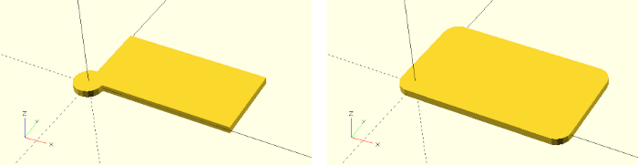
We model the border within an if-statement, such that the border only becomes part of the geometry description if the border parameter is set to true. We construct the border itself as a Boolean difference of two 2D geometries, which we subsequently convert to a 3D geometry using linear_extrude. The two 2D geometries are two Minkowski sums. The Minkowski sum of two point sets is the set of the pairwise summed points from both sets. In the case of the Minkowski sum of a rectangle and a circle, we can simply imagine that the circle is copied to all four corners of the rectangle and then the convex hull of the whole is formed (Figure {}).
We use the minkowski transformation to give the text_area-based border rounded corners. We need two surfaces. A large one that describes the outer edge of the border and a small one that describes the inner edge of the border. The smaller area is then subtracted from the larger one. Since the minkowski transformation adds the radius of the circle to the overall dimension of the text_area, we must consider the radius within the earlier offset transformation and subtract it from the border.
Since the minkowski transformation can’t deal with a situation where the radius of the circles becomes 0, we have to add another if-statement:
module stamp (
    /* ... */
){
    /* ... */

    module relief() {
        /* ... */

        // border
        if (border) {

            linear_extrude( height = stamp_depth )
            difference() {
                minkowski(){
                    offset(
                        delta = stamp_margin -
                                border_radius +
                                ((border_radius > 0) ? 0 : border_thickness)
                    )
                    text_area();

                    if (border_radius > 0)
                    circle( r = border_radius + border_thickness, $fn = 36);
                }

                minkowski(){
                    offset(delta = stamp_margin - border_radius)
                    text_area();

                    if (border_radius > 0)
                    circle( r = border_radius, $fn = 36);
                }
            }

        }
    }

    /* ... */
}
/* ... */
Now the circles within the Minkowski sums are only present in the geometry description if the radius of the circles is greater than 0. At the same time the offset transformation of the larger area is adapted in such a way that in case of a radius of zero the thickness of the border is not produced via the circle but via the offset transformation.
With this, we have completed the description of the stamp relief and can now turn to the geometry description of the stamp body:
module stamp (
    /* ... */
    stamp_relief   = true,     // generate stamp relief
    stamp_body     = true,     // generate stamp body

    body_height    = 10,       // stamp body height
    body_base      = 2,        // height of stamp body base
    body_border    = 1.6,      // wall thickness of relief mount
    body_allowance = 0.5,      // expansion of relief mount when printing in
                               // two parts
    body_inner_depth   = 1,    // depth of relief mount
    body_radius        = 1,    // stamp body edge radius
    body_taper         = 3,    // stamp body taper
    body_handle_dm     = 25,   // handle sphere diameter
    body_handle_height = 40,   // handle sphere height above body
    body_handle_collar = 3,    // lower handle collar
    body_handle_ind    = 5     // diameter of the front indicator
){
    /* ... */

    module stamp_body() {

        body_z_null = stamp_depth + stamp_relief_depth - body_inner_depth;

        module base( taper = 0) {
            minkowski() {
                offset(
                    delta = stamp_margin +
                            (border ? border_thickness : 0) +
                            body_border +
                            (stamp_relief ? 0 : body_allowance) -
                            body_radius -
                            taper
                )
                text_area();

                if (body_radius > 0)
                circle( r = body_radius, $fn = 36);
            }
        }

    }

    /* ... */
}
/* ... */
We begin by extending our module stamp by quite a number of parameters again. The parameters stamp_relief and stamp_body stand out in particular. They control whether a geometry description is generated for the relief or the stamp body. We will use this information not only when instantiating the submodules, but also within the submodule stamp_body. We refrain from a detailed description of the numerous other parameters at this point, since their meaning will become clear in the following sections.
In the submodule stamp_body we first define the variable body_z_null, which describes the height of the lower edge of the stamp body. Since the body will have a recess on the bottom side to accommodate the stamp relief, the bottom edge is not equal to stamp_depth + stamp_relief_depth but lower by body_inner_depth. Next, we define an auxiliary module base that provides a two-dimensional description of the stamp body’s base shape. Like the stamp relief, this base shape builds on text_area, which is expanded using the offset transformation and rounded using the minkowski transformation. The expansion of the base area depends on a number of parameters and considers e.g. if there is a border or not. Via the parameter taper the base area can be adjusted in the further course of the model description without having to use another offset transformation.
The check whether a stamp_relief is created together with a stamp_body has the following background: if the stamp relief is not created together with the stamp body, we assume that the stamp body and stamp relief are printed separately and joined together afterwards. In this case, the parameter body_allowance allows to adjust the size of the recess on the underside of the stamp body. Accordingly, this adjustment must also be taken into account during the expansion of the base area. If, on the other hand, the stamp relief and the stamp body are created at the same time, we assume that they are also produced in one piece and the need for adjustment is eliminated.
The main body of the stamp is created using a hull transformation, from which the relief recess is then subtracted using a Boolean difference:
module stamp (
    /* ... */
){
    /* ... */

    module stamp_body() {

        /* ... */

        // main body
        difference() {
            hull(){
                translate([
                    0,
                    0,
                    body_z_null
                ])
                linear_extrude( height = body_base )
                base();

                translate([
                    0,
                    0,
                    body_z_null + body_height
                ])
                linear_extrude( height = 0.01 )
                base( body_taper );
            }

            translate( [0, 0, stamp_depth] )
            linear_extrude( height = stamp_relief_depth)
            offset(
                delta = stamp_margin +
                        (border ? border_thickness : 0) +
                        (stamp_relief ? 0 : body_allowance)
            )
            text_area();
        }

    }

    /* ... */
}
/* ... */
The lower part of the main body consists of a base with height body_base. This creates a small edge. The upper part consists of a base reduced by body_taper, that is only a hundredth of a millimeter thick. This part serves only as a “lid”, while the side walls are created by the hull transformation. The recess for the stamp relief is created directly based on the text_area, brought to the right size with offset, positioned analogous to the base of the stamp relief and finally subtracted from the main body using a Boolean difference operation.
The only thing missing now is the stamp handle:
module stamp (
/* ... */
){
/* ... */
module stamp_body() {
/* ... */
// handle sphere
translate( [0, 0, body_z_null + body_height + body_handle_height])
sphere(d = body_handle_dm, $fn = 50);
// handle front indicator
color("Silver")
translate([
0,
body_handle_dm / 2,
body_z_null + body_height + body_handle_height
])
scale( [1, 0.5, 1] )
sphere(d = body_handle_ind, $fn = 25);
// handle neck
translate( [0, 0, body_z_null + body_height])
rotate_extrude( $fn = 50)
difference() {
square(
[body_handle_dm / 2 - body_handle_collar, body_handle_height]
);
translate([body_handle_dm / 2, body_handle_height / 2 ])
scale( [0.4, 1] )
circle( d = body_handle_height, $fn = 50 );
}
}
/* ... */
}
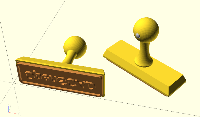
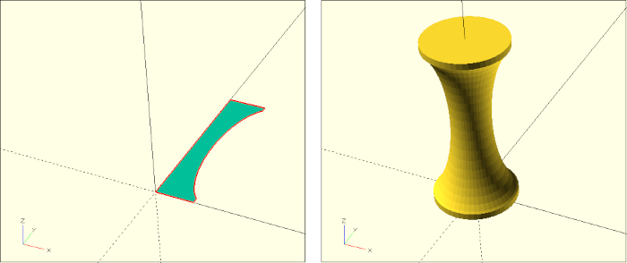
/* ... */The stamp handle consists of a ball, a neck underneath, and a tactile indicator that marks the front of the stamp. The ball consists of a suitably shifted sphere base shape. The front indicator consists of a small sphere, which we have additionally compressed to 50% in the Y-direction using the scale transformation. We describe the neck via a rotate extrude transform (Figure 8.). For this, we take a rectangle as 2D base shape and cut out a compressed circle on one side of the rectangle using a Boolean difference. Finally, we use a rotate_extrude transform to turn this 2D geometry into a concave, three-dimensional neck.
Our stamp module is now almost finished. We only have to consider the parameters stamp_relief and stamp_body when instantiating the submodules:
module stamp (
    /* ... */
){
    /* ... */

    if (stamp_relief) {
        color("Peru")
        rotate([0, stamp_body ? 0 : 180, 0])
        relief();
    }

    if (stamp_body) {
        stamp_body();
    }

}
/* ... */
In case of the stamp relief, we have added a rotate transform that ensures that the relief is flipped over should it be rendered on its own. This facilitates subsequent 3D printing of the relief.
A small tip at the end: If we want to use special Unicode characters in our text, we can encode them using OpenSCAD’s chr function. The “opposite direction” is the ord function. It returns the corresponding Unicode for a given character. Since many fonts also contain symbols as characters, it can be an easy way to use these symbols within OpenSCAD as 2D basic shapes. For example, text( chr( 9786 ) ); returns a smiling face as 2D geometry :).
We have managed to describe the stamp geometry in such a way that it automatically adapts to the dimension of the respective text. This makes the stamp module quite suitable to be used as an example for automated geometry creation via the command line. Such an approach could be used to offer the creation of custom stamps via an alternative interface.
In order to automatically generate stamps from the command line, our stamp instance must be parameterized within the .scad file using variables:
/* ... */

st  = "OpenSCAD";
stg = 10;

stamp(st,stg);
The variables must be initialized with sample values and must not remain undefined. If these conditions are met we can set these variables from the command line:
$ OpenSCAD -o stempel.stl -D 'st="3D-Printing!"' -D 'stg=15' stamp.scad The option -o stamp.stl specifies the output file. The option -D 'st="3D printing!"' sets the variable st to the value “3D printing” and the option -D 'stg=15 sets the parameter stg to 15. The last argument stamp.scad is the name of the .scad file containing our module stamp and the stamp instance parameterized with the variables st and stg.