
When designing a technical system, it regularly happens that already existing components have to be integrated. In the context of 3D printing, these are often motors, ball bearings, screws or nuts, for example. In such cases, it is helpful to measure and remodel these components and use them as mockups in the geometry description. This way, you can already see in the computer model whether all parts of the system really fit and are in the right place. If you use certain components frequently, it is worth storing them in an OpenSCAD library and then including them in the respective project using include or use.
In this project we want to take a closer look at important aspects that have to be considered if we want to create a useful OpenSCAD library. As example, we will remodel a standard clock movement and design the geometry description in such a way that it can be comfortably used as part of an OpenSCAD library.
We will learn about the 2D basic shape import as well as the 3D basic shape surface. In terms of new transformations we will use mirror and resize. Furthermore we will use the search function and learn how to create simple animations with OpenSCAD.
We start by defining a module and describing the box-shaped main body of the movement:
module clock_movement() {

    width  = 56;
    depth  = 56;
    height = 20;

    // main body
    color("Gray")
    translate( [-width / 2, -depth / 2, -height] )
    cube( [width, depth, height] );

}

clock_movement();
Since we are modeling a given physical object, we can assume the measured quantities to be fixed and therefore do not need to make them parameters of the module. Instead, we define them as variables within the module. Even though our geometry description is not very extensive so far, we have already made an important design decision. We decided to align the main body of the clock to the origin of the coordinate system in such a way that the surface of the main body is planar with the X-Y plane (displacement along the Z-axis by -height) and that later the axes of the clock movement will coincide with the Z-axis (displacement in X and Y direction by -width / 2 and -depth / 2). This alignment will not only simplify the following modeling steps, but will also improve the usability of the clock_movement module as part of an OpenSCAD library.
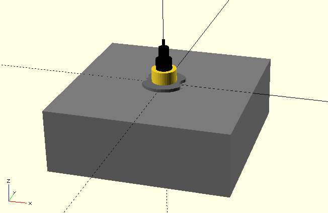
Surrounding the main axis of the movement, an alignment pattern protrudes from the main body. It consists of a flattened, notched cylinder. This alignment pattern serves to lock and align the movement when it is installed in a clock. It is therefore an important detail that should be present in our movement mockup:
module clock_movement() {

    /* ... */

    alignment_dm       = 14; // diameter of alignment pattern
    alignment_h        = 1;  // height of alignment pattern
    alignment_flat     = 1;  // recess of flattening
    alignment_notch_dm = 6;  // diameter of alignment notches
    alignment_notch_fl = 2;  // recess of notch flattening

    /* ... */

    // alignment pattern
    difference(){
        color("DimGray")
        cylinder( d = alignment_dm, h = alignment_h, $fn = 36);

        // flattening and notch
        color("Gray")
        for ( i = [0:1])
        mirror( [i, 0, 0] )
        union(){
            translate([
                alignment_dm / 2 - alignment_flat,
                -(alignment_dm + 2) / 2,
                -1
            ])
            cube([
                alignment_flat + 1,
                alignment_dm + 2,
                alignment_h + 2
            ]);

            translate([
                alignment_dm / 2 - alignment_notch_fl +
                    alignment_notch_dm / 2,
                0,
                -1
            ])
            cylinder(
                d = alignment_notch_dm,
                h = alignment_h + 2,
                $fn = 18
            );
        }
    }

}
/* ... */
We describe the alignment pattern using the basic shape cylinder, from which we subtract the flattening and notches using a Boolean difference operation. We first model the flattening and notch on one side of the main cylinder by combining a box (cube) and a cylinder using a Boolean union. We position both geometries according to their respective setbacks and ensure sufficient allowances in dimensioning (and positioning) to ensure a clean difference operation.
Since our model is symmetric with respect to the origin, we can describe the flattening and notch on the other side of the main cylinder by a combination of mirror transformation and for-loop. The parameter of the mirror transformation is a three-dimensional vector that specifies along which axis we want to mirror our geometry. If the vector is the null vector ([0, 0, 0]), no mirroring takes place. Since our loop variable i becomes 0 and 1 exactly once, we thus create both our original flattening-notch pair and the mirrored pair on the opposite side.
If the movement is installed in a clock, it is fastened via a central screw terminal. Potential clocks must therefore have an appropriate hole that can receive that screw. We will only model this screw terminal as a simple cylinder and will not include the fine thread in our model:
module clock_movement() {

    /* ... */

    screw_terminal_dm = 7.8; // screw terminal diameter
    screw_terminal_h  = 5;   // screw terminal height
                            // measured from main body

    /* ... */

    // screw terminal
    color("Gold")
    cylinder( d = screw_terminal_dm, h = screw_terminal_h, $fn = 36);

}
/* ... */
The only thing missing from our geometry of the movement are the three axes for the hour, minute and second hands:
module clock_movement() {

    /* ... */

    hour_axle_dm = 5.1; // hour axle diameter
    hour_axle_h  = 8.3; // hour axle height

    minute_axle_dm = 3.2;  // minute axle diameter
    minute_axle_h  = 12.1; // minute axle height

    second_axle_dm = 1;    // second axle diameter
    second_axle_h  = 14.5; // second axle height

    /* ... */

    // axles
    color("Black") {
        cylinder( d = hour_axle_dm,   h = hour_axle_h,   $fn = 36);
        cylinder( d = minute_axle_dm, h = minute_axle_h, $fn = 36);
        cylinder( d = second_axle_dm, h = second_axle_h, $fn = 18);
    }

}
/* ... */
Like the screw terminal, we model the axes as simple cylinders. A small side note: the use of the color transformation (color("Black")) here is an example that transformations can also be applied to geometry sets ({ ... }).
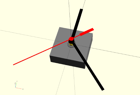
We could now already use our remodeled clock movement as a mockup object when designing a clock (Figure 6.). For the design of a clock, however, it would be much more convenient if our model also had a set of hands. This would allow us to see right away, for example, whether the dial has the correct proportions. So let’s give our clockwork model a set of hands:
module clock_movement( time = [12, 0, 0] ) {

    /* ... */

    // hands
    rotate( [0, 0, -360 * time[0] / 12] )
    translate( [0, 0, hour_axle_h - 1] )
    hour_hand();

    rotate( [0, 0, -360 * time[1] / 60] )
    translate( [0, 0, minute_axle_h - 1] )
    minute_hand();

    rotate( [0, 0, -360 * time[2] / 60] )
    translate( [0, 0, second_axle_h ] )
    second_hand();

    module hour_hand( ) {

        h = 0.4;   // height
        l = 72.35; // length
        r = 67.6;  // radius
        b = 5;     // width
        dm = 9.5;  // diameter

        color("Black")
        union() {
            cylinder( d = dm, h = h, $fn = 36 );

            translate( [-b / 2, 0, 0] )
            cube( [b, r, h] );
        }
    }

    module minute_hand() {

        h  = 0.4;   // height
        l  = 100.5; // length
        r  = 96;    // radius
        b  = 4;     // width
        dm = 9;     // diameter

        color("Black")
        union() {
            cylinder( d = dm, h = h, $fn = 36 );

            translate( [-b / 2, 0, 0] )
            cube( [b, r, h] );
        }
    }

    module second_hand() {

        b1  = 1.25; // width front part
        l1  = 95;   // length front part
        b2  = 1.25; // width neck
        l2  = 15;   // length neck
        b3  = 4.6;  // width back part
        l3  = 24;   // length back part
        dm  = 7.1;  // diameter
        h   = 0.4;  // material thickness

        color("Red")
        union() {
            cylinder( d = dm, h = h, $fn = 36);

            translate( [-b1 / 2, 0, 0] )
            cube( [b1, l1, h] );

            translate( [-b2 / 2, -l2, 0] )
            cube( [b2, l2, h] );

            translate( [-b3 / 2, -(l2 + l3), 0] )
            cube( [b3, l3, h] );
        }
    }

}
/* ... */
We have given our module clock_movement a parameter time, which expects a testtime as a three-dimensional vector with [hours, minutes, seconds]. For each hand we defined a separate submodule, so that we can simply move the respective hand geometries to the appropriate height and rotate them around the Z-axis according to time. To do this we convert the respective time data into corresponding angles.
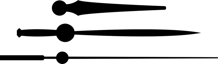
The individual hands were measured, and the measured values were stored in variables within the submodules. The hands were then modeled using a combination of basic 3D shapes. Although the hands have a relatively simple shape (Figure 6.1), this procedure is relatively time consuming and results in a convoluted geometry description.
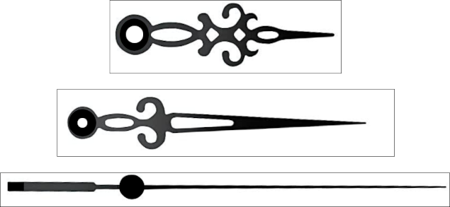
Since it is quite common for a clock movement to be sold with a selection of different hand styles, the previous approach is not particularly effective. An alternative way to modeling the hands consists in drawing the hands in an external drawing program and saving them as a .svg file (Figure 6.). Using the import function of OpenSCAD such external drawings can then be loaded as a 2D basic shape:
module clock_movement( time = [12, 0, 0], hand_style = "modern") {

    /* ... */

    module stundenzeiger() {

        h = 0.4;   // height
        l = 72.35; // length
        r = 67.6;  // radius
        b = 5;     // width
        dm = 9.5;  // diameter

        if (hand_style == "modern") {
            /* ... */
        }

        if (hand_style == "deco") {
            color("Black")
            linear_extrude(height = h)
            import("stunden.svg");
        }
    }

    module minutenzeiger() {

        h  = 0.4;   // height
        l  = 100.5; // length
        r  = 96;    // radius
        b  = 4;     // width
        dm = 9;     // diameter

        if (hand_style == "modern") {
            /* ... */
        }

        if (hand_style == "deco") {
            color("Black")
            linear_extrude(height = h)
            import("minuten.svg");
        }
    }

    module sekundenzeiger() {

        b1  = 1.25; // width front part
        l1  = 95;   // length front part
        b2  = 1.25; // width neck
        l2  = 15;   // length neck
        b3  = 4.6;  // width back part
        l3  = 24;   // length back part
        dm  = 7.1;  // diameter
        h   = 0.4;  // material thickness

        if (hand_style == "modern") {
            /* ... */
        }

        if (hand_style == "deco") {
            color("Black")
            linear_extrude(height = h)
            import("sekunden.svg");
        }
    }

}
The module clock_movement received an additional parameter hand_style, with which the type of the hands can be set. Inside the hand submodules we use if-statements to differentiate the different styles. The style “modern” refers to the hands that we manually modeled before. The style “deco”, however, loads the hand shapes from .svg files and then converts them into a 3D geometry using linear_extrude. The import function behaves here like any other 2D basic shape and can be used in the same way, e.g. it can be transformed.
Using the SVG import for complicated 2D geometries is generally the best way to use such geometries in OpenSCAD. However, it is not without effort to create such geometries even in programs specialized for this task such as Inkscape. In our use case, such an effort is not necessarily justified, since we use the hands primarily for visualization and have no requirements other than sound overall dimensions. In such a case, we can trade working time for computing time and let OpenSCAD create the 2D geometries directly from photos (Figure 6.) for us. Unfortunately, the computation and memory required are not to be underestimated and it may happen that the procedure described below is not practical on a computer that is too weak. Fortunately, OpenSCAD caches the result of its calculations so they don’t have to be done each time a preview is run!
Let’s see how we can extract our hands from .png images:
module clock_movement( time = [12, 0, 0], hand_style = "modern") {
/* ... */
module stundenzeiger() {
/* ... */
if (hand_style == "modern") {
/* ... */
}
if (hand_style == "deco") {
/* ... */
}
if (hand_style == "classic") {
lc = 61;
color("Black")
png_zeiger( "stunden.png", lc, h, [-9.5, -6.75, 0]);
}
}
module minutenzeiger() {
/* ... */
if (hand_style == "modern") {
/* ... */
}
if (hand_style == "deco") {
/* ... */
}
if (hand_style == "classic") {
lc = 84;
color("Black")
png_zeiger("minuten.png", lc, h, [-9, -6.75, 0]);
}
}
module sekundenzeiger() {
/* ... */
if (hand_style == "modern") {
/* ... */
}
if (hand_style == "deco") {
/* ... */
}
if (hand_style == "classic") {
lc = 123;
color("Black")
png_zeiger("sekunden.png", lc, h, [-4,-36.8,0] );
}
}
module png_hands(filename, length, height, displacement) {
translate( displacement )
linear_extrude( height = height )
resize( [0, length], auto = true )
projection( cut = true )
translate( [0, 0, 75] )
surface( filename, invert=true );
}
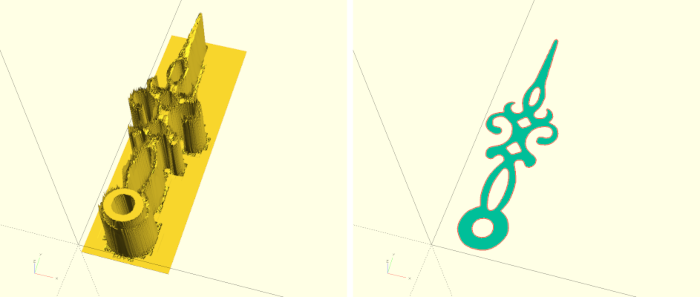
}The new submodule png_hands creates a hand from a .png image file. First we use the surface geometry to create a height relief from a .png image file. Normally, light colors are interpreted as “high” and dark colors as “low”. The parameter invert reverses this interpretation. We now move the resulting height relief upwards in such a way that it intersects the X-Y plane at a suitable point (Figure 6. on the left). If we now apply the projection transformation to the height relief, we intersect the relief in the X-Y plane and create a sufficiently clean 2D geometry from the intersection (Figure 6. right). Unfortunately, the resulting 2D geometry does not have the correct size. Therefore we use the resize transformation to scale the geometry to a desired length. We let the width to be determined automatically by setting it to 0. Afterwards we can extrude the now correctly scaled 2D geometry to the desired height and move it in such a way that the axis of the hand lies at the origin of the coordinate system.
To avoid spending this much compute every time you use the clock_movement module, it may be worthwhile to perform the calculation once and, after the resize operation, save the resulting 2D shape with OpenSCAD as an .svg file and then load it using import as described above.
In principle, our clock movement module is now ready and could be included and used in other geometry descriptions using use. However, there is a flaw in our current approach. If you want to use the module in another geometry description, then you almost inevitably need information about the dimensions of the movement. However, these are not available to the other geometry description. An ad-hoc solution would be to open the movement module file and find out the values manually. A slightly less inelegant solution would be to define the variables defined inside the clock_movement module outside of the module. If you then include the .scad file using include instead of use, you can access these variables. However, there are two major problems with this solution. First, there can be name collisions. For example, we have defined the variables width, depth and height for the movement. There is a good chance that you would like to use these names in another project as well. It becomes even more difficult if you want to keep several modules in a library file, which all need their own variables. You can solve this problem with a strict naming convention. However, this is not a nice solution. The second big problem is that you have no control over which variables or information are “exported”. The choice between include and use is a choice between “everything” or “nothing”. If you choose “everything”, then you lose the ability to define “local” variables outside of modules that are only available within the library.
A better solution to this problem may be as follows:
// clock_movement constants
movement_data = [
    ["width",  56], // width of the main body
    ["depth",  56], // depth of the main body
    ["height", 20], // height of the main body

    ["alignment_dm",       14], // alignment diameter
    ["alignment_h",         1], // alignment height
    ["alignment_flat",      1], // alignment flattening
    ["alignment_notch_dm",  6], // alignment notch diameter
    ["alignment_notch_fl",  2], // alignment notch flattening

    ["screw_terminal_dm", 7.8], // screw terminal diameter
    ["screw_terminal_h",  5  ], // screw terminal height
                               // measured from main body

    ["hour_axle_dm", 5.1], // hour axle diameter
    ["hour_axle_h",  8.3], // hour axle height

    ["minute_axle_dm",  3.2], // minute axle diameter
    ["minute_axle_h",  12.1], // minute axle height

    ["second_axle_dm",  1  ], // second axle diameter
    ["second_axle_h",  14.5]  // second axle height
];

function movement_dim( name ) =
    [ for (d = movement_data) if (d[0] == name) d[1] ][0];
We create an array with data that we want to make available for our geometry. In our case, all important dimensions of our clock movement are in the array movement_data. To be able to access this data even if the library was included with use, we have to provide a function (here: movement_dim) for access. This function gets as parameter the name of the data entry whose data we want to read. One way to implement such a function is to use a generative for-loop. We scan with the loop variable d through the array movement_data and add an element (d[1]) to our result array if the passed name corresponds to the name of the array entry (if (d[0] == name)). The result of this generative for-loop is an array that contains only one entry: exactly the data we would like to read out of movement_data. What remains now is to access this one entry of the array. This is done by the subsequent [0] statement.
For more complicated searches over data OpenSCAD provides the search command. We can see how this can be used in the following example:
// hand_style constants
hands_data = [
    ["style",    "modern", "classic", "deco"],

    ["hour_l",      72.35,        61,   62.9],
    ["hour_r",       67.6,      56.6,  58.65],
    ["hour_w",          5,       1.5,      2],
    ["hour_h",        0.4,       0.4,    0.4],

    ["minute_l",    100.5,        84,  101.5],
    ["minute_r",       96,      79.5,  74.62],
    ["minute_w",        4,         1,      1],
    ["minute_h",      0.4,       0.4,    0.4],

    ["second_l",      134,       123,    120],
    ["second_r",       95,      88.4,  85.66],
    ["second_w",     1.25,       0.6,    0.7],
    ["second_h",      0.4,       0.4,    0.4]
];

function hands_dim( name, stil ) =
    let (
        row = search( [name], hands_data)[0],
        col = search( [stil], hands_data[0])[0]
    ) hands_data[row][col];
We have summarized all data of the different hand types in one array. The access function hands_dim has two parameters now. One for the name of the value and one for the name of the style. We use the expression let to find the indices of the row and column in which the requested data is located by using the search command. As before, a trailing [0] appears in our description, as the result returned by search is an array of indices and we are only interested in the first element of the array here. The first parameter to search is a list or array of search terms. Since we only want to search for one string at a time (name or style), the first parameter is written as an array with only one entry. The second parameter is the array to be searched. When searching for the matching row, we want to search through the complete field hands_data. In this case search looks by default only at the first entry of the individual array entries, which are the names of the records. To find the matching column, we only search through the first entry of hands_data, which is also an array. This way we get two indices row and column, with which we can then read the data we are looking for from the field hands_data and return it as the function’s value (hands_data[row][column]).
Of course it makes sense to use the functions movement_dim and hands_dim also within the module clock_movement for the initialization of the variables:
module clock_movement( time = [12, 0, 0], hand_style = "modern") {

    width  = clockwork_dim("width");
    depth  = clockwork_dim("depth");
    height = clockwork_dim("height");

    alignment_dm       = clockwork_dim("alignment_dm");
    alignment_h        = clockwork_dim("alignment_h");
    alignment_flat     = clockwork_dim("alignment_flat");
    alignment_notch_dm = clockwork_dim("alignment_notch_dm");
    alignment_notch_fl = clockwork_dim("alignment_notch_fl");

    screw_terminal_dm = clockwork_dim("screw_terminal_dm");
    screw_terminal_h  = clockwork_dim("screw_terminal_h");

    hour_axle_dm = clockwork_dim("hour_axle_dm");
    hour_axle_h  = clockwork_dim("hour_axle_h");

    minute_axle_dm = clockwork_dim("minute_axle_dm");
    minute_axle_h  = clockwork_dim("minute_axle_h");

    second_axle_dm = clockwork_dim("second_axle_dm");
    second_axle_h  = clockwork_dim("second_axle_h");

    /* ... */

    module stundenzeiger() {

        h = hands_dim("hour_h",hand_style);
        l = hands_dim("hour_l",hand_style);
        r = hands_dim("hour_r",hand_style);
        b = hands_dim("hour_w",hand_style);

        /* ... */
    }

    module minutenzeiger() {

        h = hands_dim("minute_h",hand_style);
        l = hands_dim("minute_l",hand_style);
        r = hands_dim("minute_r",hand_style);
        b = hands_dim("minute_w",hand_style);

        /* ... */
    }

    module sekundenzeiger() {

        h = hands_dim("second_h",hand_style);
        l = hands_dim("second_l",hand_style);
        r = hands_dim("second_r",hand_style);
        b = hands_dim("second_w",hand_style);

        /* ... */
    }

    /* ... */

}OpenSCAD offers a simple way to animate our geometries and, if chosen, save the animation as an image sequence. To animate our clockwork, we can extend our geometry description outside the module clock_movement as follows:
/* ... */

function get_time( tick ) = [(tick / 3600) % 12, (tick / 60) % 60, tick % 60];

clock_movement( get_time($t * 43200) , "modern");
We define a function get_time to which we can give a number of seconds as a parameter and get a three-dimensional vector with hours, minutes and seconds as a result. The % operator stands for the modulo or remainder of a division and ensures that the minute and second values always lie in the range 0 to 59 and that the hour value always lies in the range 0 to 11. We now pass the expression ‘$t * 43200’ as a parameter to the get_time function. The special variable $t returns the current time within an animation. The animation time is always a floating point number that runs between 0 and 1. Thus, we scale the animation time with the expression to the range 0 to 43200 (12 hours have 43200 seconds).
To start the animation, you have to make the animation menu visible (View -> Animate). Three input fields Time, FPS and Steps will then appear under the output window. As Steps we enter 43200 and as FPS a 1. Our clock should start moving and ticking away. You can stop the animation by hiding the animation menu (View -> Animate). If you check the Dump Pictures checkbox, every animation step will be saved as a numbered .png file. These files can then be used afterwards, e.g., to convert them into a video file. Under Linux this can be done with the program ffmpeg.