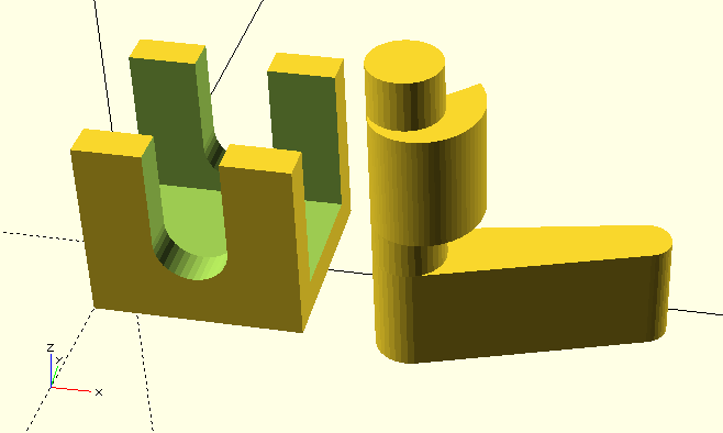
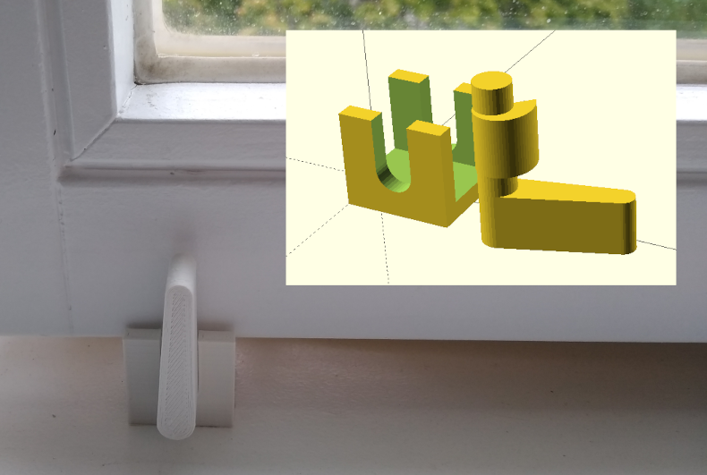
In this project we design a window stopper with a rotating wedge. If you turn the lever of the stopper, the wedge jams the window upwards and locks it in place.
We will learn about a new variant of the for-loop (generative for), with which we can create function-based arrays. In this context we will also learn about the keyword let and see how we can transform the generated data into a geometry using the 2D basic form polygon. Last but not least, we will also learn what the hull transformation is all about.
Let’s start, as we are used to by now, with the definition of a module window_stopper. Since we expect quite a number of parameters, we will choose a vertical parameter arrangement again. Furthermore, we prepare some empty submodules to split our geometry description into several parts:
// a window stopper with rotating wedge
// (all sizes in millimeter)

module window_stopper(

	/* parameters */

){

    $fn = 36;

    module window() {
    }

    module stopper_case() {
    }

    module stopper() {
    }

    window();
    stopper_case();
    stopper();

}

window_stopper(

	/* parameters */

);
Even though we will use each submodule only once, the subdivision into several submodules will help us when we later want to generate the individual geometry parts, e.g. for a 3D print. The window module will be a purely auxiliary module, in which we model the bottom edge of the window as an orientation guide. In the stopper_case module we will describe the housing of the window stopper and in the stopper module we will define the rotating wedge as well as its lever. In addition to the submodules and their three instances, we defined the special variable $fn at the module level. This way we set the level of detail of all curved geometries in our module.
Let’s start our geometry description with the auxiliary module window:
/* ... */
module window_stopper(
    window_thickness,         // thickness of window frame
    windowsill_dist,          // distance between window and windowsill
){

    $fn = 36;

    module window() {
        color("LightSkyBlue")
        translate( [-20, -window_thickness / 2, windowsill_dist] )
        cube( [100, window_thickness, 0.1] );
    }

	/* ... */

}
/* ... */
We have added the parameters window_thickness and windowsill_dist to our module. They describe the thickness of the window and the distance of the lower edge of the window to the window sill. In the submodule window we only describe this lower edge of the window with a 0.1 millimeter thin box (cube). We set the width of the cube to an arbitrary 10cm, as this dimension is not relevant for the construction of the stopper. Using the translation transform we bring the cube to the height windowsill_dist and center it over the x-axis (-windowsill depth / 2). To visually set off our auxiliary object from the rest of the geometry, we give it a nice shade of blue. Since we use the submodule only once and do not need to parameterize it, the parameter list is empty. We can access the parameters of the parent module window_stopper directly and do not have to pass them on using local parameters. This also applies to variables defined in the parent module. We will take advantage of this in the next step.
The geometry description of the holder is a bit more involved. In essence, however, the holder consists only of a simple box (cube), from which we subtract a series of suitably rotated and displaced basic shapes (cube and cylinder) using a Boolean difference operation:
/* ... */
module window_stopper(
    window_thickness,         // thickness of window frame
    windowsill_dist,          // distance between window and windowsill
    windowsill_adj     = 0,   // adjustment for windowsill distance
    stopper_width      = 30,  // width of the stopper
    material_thickness = 5,   // material thickness of the stopper
    window_overlap     = 7,   // overlap of stopper and window
    axle_dm            = 10,  // axle diameter
    axle_clearance     = 0.5, // axle clearance towards bushing
){

    $fn = 36;
    axle_height =
        material_thickness + (windowsill_dist - material_thickness) / 2;

	/* ... */

    module stopper_case() {
        case_size = [
            stopper_width,
            window_thickness + 2 * material_thickness,
            windowsill_dist + window_overlap
        ];

        translate( [0, -case_size.y / 2, 0] )
        difference() {
            cube( case_size );

            translate( [-1, material_thickness, material_thickness] )
            cube( [case_size.x + 2, window_thickness, case_size.z] );

            axle_bushing = axle_dm + axle_clearance;

            translate( [case_size.x / 2, -1, axle_height] )
            rotate( [-90, 0, 0] )
            cylinder( d = axle_bushing, h = case_size.y + 2);

            translate( [(case_size.x - axle_bushing) / 2, -1, axle_height] )
            cube( [axle_bushing, case_size.y + 2, case_size.z] );
        }

        translate( [0, -case_size.y / 2, -windowsill_adj] )
        cube( [case_size.x, case_size.y, windowsill_adj] );
    }

	/* ... */

}
/* ... */
Our parameter list got a lot of new members. The parameter windowsill_adj allows a later readjustment of the window stopper. The parameters stopper width and material thickness define the width of the stopper case and the material thickness of the sides and the bottom of the case. The parameter window_overlap defines how far the stopper case should overlap laterally with the window. The parameters axis_dm and axis_clearance define the diameter of the axis of the rotating wedge and the size of the gap between the axis and its bearing in the stopper case.
Inside of the module window stopper we define the variable axis_height at a module-wide level. We will use the variable in both the submodule stopper_case and in the submodule stopper. We position the axis halfway between the window sill and the lower edge of the window, taking the material thickness of the stopper case into account. In the submodule stopper_case we define the variable case_size, which describes the dimension of our case as a three-dimensional vector that depends on window dimensions, material thickness and window overlap.
We describe the geometry of the stopper case via a Boolean difference operation. The main body, from which we subtract the other geometries, is a simple box. It has the outer dimensions of the stopper case (cube( case_size );). Subsequently, we subtract a box that has a depth matching that of the window and that is slightly wider than our main body (case_size.x + 2). We position the box upwards as well as inwards by the material thickness using a translate transformation. This turns the basic body into a U-profile that can later be moved along the window edge during operation of the stopper. Note the small displacement in the X direction (-1) to ensure a clean difference operation.
Next, we have to subtract the axle bearing from our stopper case. Since the bearing should be slightly larger in diameter than the axle itself, we define the variable axle_bushing as the sum of axle diameter and axle clearance. The axle bearing consists of a cylinder and a box (cube). The cylinder gets the diameter axle_bushing and a height equal to the depth of the cube plus a small allowance. Since the basic shape cylinder starts out perpendicular to the X-Y plane, we first have to rotate the cylinder around the X-axis onto its side. Afterwards we can move the cylinder by means of translate to the center of the case width (case_size.x / 2) and the axis_height defined earlier. Corresponding to the allowance in cylinder height, we perform a small translation (-1) in the Y direction to ensure a clean difference operation. The second part of the axle bearing consists of a box, which is as wide as the cylinder (axle_bushing) and is cut above the axle from the stopper case. Since the basic shape cube was created without center = true, we have to consider its width when moving the box to the center of the stopper case ((case_size.x - axle_bushing) / 2). Apart from this, the positioning of the box is analogous to that of the cylinder before. Again we take care that the difference operation can run cleanly (allowance in depth and corresponding displacement).
Now that we have completed the stopper case description inside the Boolean difference operation, the last remaining step is to center the case on the X-axis by prefixing the difference operation with a corresponding translation.
In order to be able to readjust the distance between the window sill and the window in another, simpler way, we define a base outside of the difference operation that can grow below the stopper case if necessary (parameter windowsill_adj). This base consists of a simple box (cube), which has the base area of the stopper case and is windowsill_adj high. To make it “grow” downwards, we use a translate transform to move it by -windowsill_adj along the Z-axis. With the same transformation we also center the base on the X-axis (-case_size.y / 2);
We have finished the submodule stopper_case and can now turn to the submodule stopper. Since the module uses a number of new OpenSCAD functions, we want to proceed step by step:
/* ... */
module window_stopper(
    window_thickness,         // thickness of window frame
    windowsill_dist,          // distance between window and windowsill
    windowsill_adj     = 0,   // adjustment for windowsill distance
    stopper_width      = 30,  // width of the stopper
    material_thickness = 5,   // material thickness of the stopper
    window_overlap     = 7,   // overlap of stopper and window
    axle_dm            = 10,  // axle diameter
    axle_clearance     = 0.5, // axle clearance towards bushing
    wedge_start_r      = 0,   // wedge start radius
    wedge_end_r        = 11,  // wedge end radius
    wedge_angle        = 42,  // start angle of wedge
    lever_depth        = 15,  // depth of lever
    lever_length       = 40,  // length of lever
    lever_angle        = 15,  // start angle of lever
){

    $fn = 36;
    axle_height =
        material_thickness + (windowsill_dist - material_thickness) / 2;

	/* ... */

    module stopper( angle = 0 ) {
        axle_length = window_thickness + 2 * material_thickness + 2;

        translate( [stopper_width / 2, -axle_length / 2, axle_height] )
        rotate( [-90, 0, 0] )
        cylinder( d = axle_dm, h = axle_length );

		/* ... */
    }

	/* ... */

}
/* ... */
For the stopper we have defined another set of parameters. The three parameters wedge_start_r, wedge_end_r and wedge_angle specify properties of the rotating wedge. The parameters lever_depth, lever_length and lever_angle are associated with the stopper lever that will turn the rotating wedge. As we did in the stopper_case module, we will also use the variable axis_height in this submodule. In addition, we have defined the variable axis_length inside the stopper submodule. It corresponds to the width of the case plus two millimeters, making the axle protrude one millimeter (front and back) from the stopper case. The axle itself is modeled using the basic shape cylinder and moved to the correct position using rotate and translate transformations. The submodule stopper also has a parameter angle, which we will use later to test the function of the rotating wedge.
Next, we will model the rotating wedge, which will become part of the axle. To this end, we will first use a special variant of the for-loop to create an array of 2D points that describe the shape of the rotating wedge in two dimensions. Then we pass this set of points to the 2D basic shape polygon, which creates a 2D geometry from the set of points. We can then extrude this geometry using linear_extrude and move it to the desired location using the usual rotate and translate transformations:
/* ... */
module window_stopper(
	/* ... */
){

    $fn = 36;
    axle_height =
        material_thickness + (windowsill_dist - material_thickness) / 2;

	/* ... */

    module stopper( angle = 0 ) {
        axle_length = window_thickness + 2 * material_thickness + 2;

        translate( [stopper_width / 2, -axle_length / 2, axle_height] )
        rotate( [-90, 0, 0] )
        cylinder( d = axle_dm, h = axle_length );

        points = [
            for (i = [0:5:360])
            let (
              radius = wedge_start_r + (wedge_end_r - wedge_start_r) * i / 360
            )
            [ cos( i ) * radius, sin( i ) * radius ]
        ];

        wedge_width = window_thickness - 2;

        translate( [stopper_width / 2, -wedge_width / 2, axle_height] )
        rotate( [-90, 0, 0] )
        rotate( [0, 0, wedge_angle + angle] )
        linear_extrude( height = wedge_width )
        polygon(points);

		/* ... */
    }

	/* ... */

}
/* ... */
The central element in the geometry description above is the variable points, to which we assign an array (points = [ ... ];). The goal is to pass this array as a parameter to the 2D basic shape polygon. The 2D base shape polygon expects an array of 2D points or two-dimensional vectors:
	points = [ [x0,y0], [x1,y1], ..., [xN,yN] ];

	polygon( points );
It’s easy to lose track with all those square brackets. The “outer” array consists of the square bracket at the very beginning and the one at the very end. Then inside, separated by commas, are the individual two-dimensional vectors with their x and y values. For simple 2D shapes, you could define such a set of points by hand or have them generated by an external program.
For our rotating wedge, we take a different approach and use a generative for-loop:
    points = [
        for (i = [0:5:360])
        let ( radius = wedge_start_r + (wedge_end_r - wedge_start_r) * i / 360 )
        [ cos( i ) * radius, sin( i ) * radius ]
    ];
The first line of the expression is similar to that of a regular for-loop. We define the loop variable i and assign it a range running from 0 to 360 in steps of 5 (for (i = [0:5:360])). The next line contains something new. The OpenSCAD expression let( ... ) allows us to define one or more variables which are set anew in each loop iteration, just like it happens with the loop variable itself. In our case, we define the variable radius and give it a value that increases steadily as the loop progresses. This way, radius has the value wedge_start_r at the beginning of the loop and the value wedge_end_r at the end of the loop. The formula can be described roughly like this: we start with wedge_start_r and want to end up at wedge_end_r. The difference or the distance between wedge_end_r and wedge_start_r is (wedge_end_r - wedge_start_r). To approach the value of wedge_end_r step by step, we need only a fraction of this distance (i / 360) in each step. When i has reached 360, our fraction is 360 / 360, i.e. 1. Before that, i is smaller than 360 and thus results in a value smaller than 1 for the respective intermediate steps.
So now we have a variable radius, which becomes increasingly larger. Where do our points come from? We find them in the third line of our generative for-loop ([ cos( i ) * radius, sin( i ) * radius ]). The third line is a template of a single array entry. In our case we want this to be a two-dimensional vector ([ .. , .. ]). The x-value of the vector is cos( i ) * radius and the y-value is sin( i ) * radius. So here we use both the loop variable i and the variable radius defined with let. For each step of the for-loop, this template vector is filled with the current values of i and radius, and is then added to the array. If you want to have a look at the generated array, you can insert the OpenSCAD command echo( points ); below (e.g.) the definition of points and run a preview (F5). The content of points will then be output in the console window of OpenSCAD.
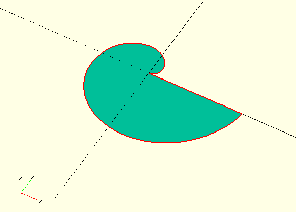
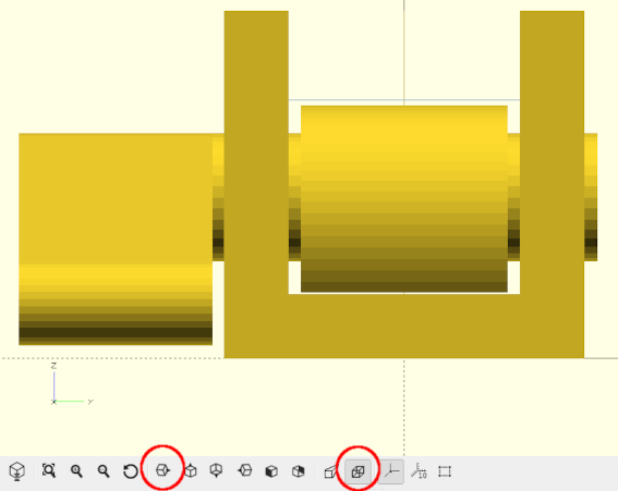
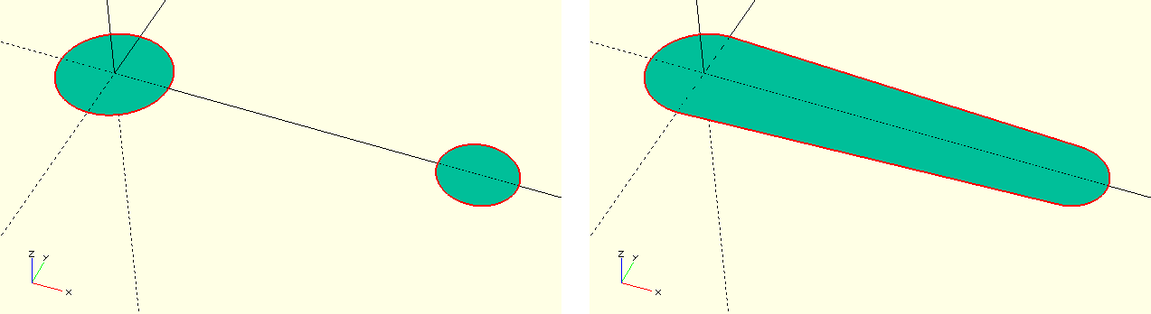
If you now pass the variable points as a parameter to the 2D basic shape polygon, the passed set of points defines a two-dimensional geometry (Figure 5.). We can then use this geometry like any other basic two-dimensional shape. To describe our rotating wedge, we extrude the shape using linear_extrude to a length of wedge_width, which we derived from window_depth. Next, we perform a rotation around the Z-axis (rotate( [0, 0, wedge_angle + angle] )). This rotation serves two purposes. First, we need to make sure that our wedge does not collide with the stopper case. For this, we need to find a suitable value for wedge_angle (Figure {}}). Second, we rotate by the angle parameter to test the functionality of our rotating wedge later. Thus we combine both angles with an addition.
We perform a second rotation around the X-axis to get the rotating wedge horizontal and then move it to the appropriate location using a translate transformation.
Having finished the rotating wedge we can now turn to modeling the lever as last part of the stopper submodule. Here we will get to know the hull transformation:
/* ... */
module window_stopper(
	/* ... */
){

    $fn = 36;
    axle_height =
        material_thickness + (windowsill_dist - material_thickness) / 2;

	/* ... */

    module stopper( winkel = 0 ) {
        axle_length = window_thickness + 2 * material_thickness + 2;

        translate( [stopper_width / 2, -axle_length / 2, axle_height] )
        rotate( [-90, 0, 0] )
        cylinder( d = axle_dm, h = axle_length );

        points = [
            for (i = [0:5:360])
            let (
              radius = wedge_start_r + (wedge_end_r - wedge_start_r) * i / 360
            )
            [ cos( i ) * radius, sin( i ) * radius ]
        ];

        wedge_width = window_thickness - 2;

        translate( [stopper_width / 2, -wedge_width / 2, axle_height] )
        rotate( [-90, 0, 0] )
        rotate( [0, 0, wedge_angle + angle] )
        linear_extrude( height = wedge_width )
        polygon(points);

        translate( [stopper_width / 2, -axle_length / 2 + 0.1, axle_height] )
        rotate( [0, lever_angle + angle, 0] )
        rotate( [90, 0, 0] )
        linear_extrude( height = lever_depth )
        hull() {
            circle( d = axle_dm );
            translate( [lever_length - axle_dm / 2 - axle_dm / 3, 0, 0] )
            circle( d = axle_dm * 0.66 );
        }
    }

	/* ... */

}
/* ... */
The hull transformation acts similarly to Boolean operations on a geometry set ({ ... }). The transformation generates the joint convex hull over the geometries contained in the set (Figure {}}). The hull transformation can be applied to both 2D and 3D geometries.
For the description of the lever we use the 2D version and generate the convex hull of two circles. We extrude the resulting basic shape of the lever using linear_extrude and rotate the whole thing around the x-axis (rotate( [90, 0, 0] )). If we prepend a ! sign to the rotate transformation and run a preview (F5), we see that the Y-axis passes exactly through the center of rotation of the lever. We can now use a second rotate transformation (rotate( [0, lever_angle + angle, 0] )) to rotate the lever to its initial position, which is determined by the parameter lever_angle. As with the rotating wedge, we also rotate by the test parameter angle. This way, the rotating wedge and the lever will turn together when we test the function of the stopper using the parameter angle. We complete the geometry description of the lever by moving it to the appropriate position using a transle transformation. Note the slight addition of 0.1 along the Y-axis to ensure that lever and axle are connected.
We did it. The geometry description for our window stopper is complete! At this point, we should test whether the rotating wedge will actually press under the window. We can check this by turning lever and rotating wedge by 100 degrees counterclockwise with our test parameter angle of the stopper module:
/* ... */
module window_stopper(
	/* ... */
){

	/* ... */

    window();
    stopper_case();
    stopper( - 100);

}
/* ... */
If everything went right, the rotating wedge should now penetrate through the blue box of the window’s bottom edge (after running a preview (F5)).
To print our window stopper, we need to have the stopper_case and stopper submodules rendered separately. The easiest way to do this is to temporarily prepend a ! character in front of the respective module instance. If we then trigger a render (F6), we can export the single geometry created in this way as a .stl file (F7).
Alternatively, the module window_stopper can be extended by a parameter print_version and a corresponding repositioning of the modules stopper_case and stopper by means of an if-statement:
/* ... */
module window_stopper(
	/* ... */
    print_version        = false
){

	/* ... */

    if (print_version) {
        stopper_case();

        translate([
            stopper_width,
            0,
            (window_thickness + 2 * material_thickness + 2) / 2 +
                lever_depth - 0.1
        ])
        rotate( [90, 0, 0] )
        stopper();
    } else {
        window();
        stopper_case();
        stopper( - 100);
    }

}
/* ... */
If print_version is true we rotate the stopper module to a suitable print orientation and translate it in a way that aligns the footpoints of stopper_case and stopper to the same height. In addition we make sure that the geometries do not overlap (Figure 5.).