
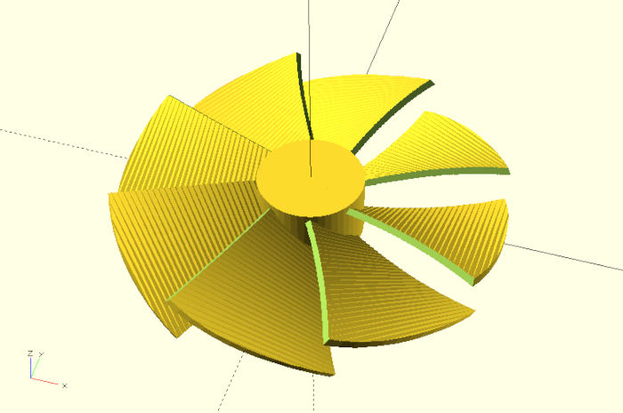
In this project we want to construct a parameterizable fan wheel, in which the angle of attack and the torsion of the blades are adjustable in particular.
We will learn about a new property of the linear_extrude transformation and use the mathematical functions abs and atan.
Let’s start with the definition of a module fan_wheel, a set of parameters and a submodule blade, where we will describe the geometry of a single blade of the fan wheel:
module fan_wheel(
outer_radius = 55,
inner_radius = 15,
blade_count = 8,
outer_width = 50,
inner_width = 20,
thickness = 2,
twist = -30,
angle_of_attack = 45,
){
module blade() {
}
blade(); // debug
}
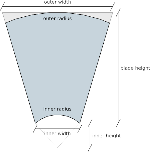
fan_wheel();Except for the parameter blade_count, which sets the number of fan blades, all other parameters refer to geometrical properties of a single blade. Figure 12. shows schematically which properties of a blade are refered to by the parameters outer_radius, inner_radius, outer_width and inner_width. We will derive the values inner_height and blade_height in figure 12. later. The parameters twist and angle_of_attack affect the twist of the fan blade and the angle of the blade at the fan hub. The parameter thickness sets the thickness of the fan blade.
Inside the module fan_wheel we have created the submodule blade as well as a test instance of this submodule. Let’s start with the geometry description of a single blade:
module fan_wheel(
    /* ... */
){

    module blade() {

        inner_height =
            cos(
                asin( inner_width / ( 2 * inner_radius ) )
            ) * inner_radius;

        blade_height = outer_radius - inner_height;

        translate( [0, inner_height, 0] )
        rotate( [-90, 0, 0] )
        linear_extrude(
            height    = blade_height,
            twist     = twist,
            slices    = 10 ,
            convexity = 10
        )
        square( [outer_width, thickness], center = true );

    }

    blade(); // debug
}
/* ... */
We first calculate the values inner_height and blade_height (Figure 12.). The inner_height is the point where the vertical with distance inner_width / 2 from the origin and the circle with inner_radius meet. To calculate the inner_height we need the angle between the radius and the vertical at this intersection (asin( inner_width / ( 2 * inner_radius )). Then we can determine the inner_height using the cosine and the inner_radius. The blade_height is the remainder of the distance from inner_height to outer_radius.
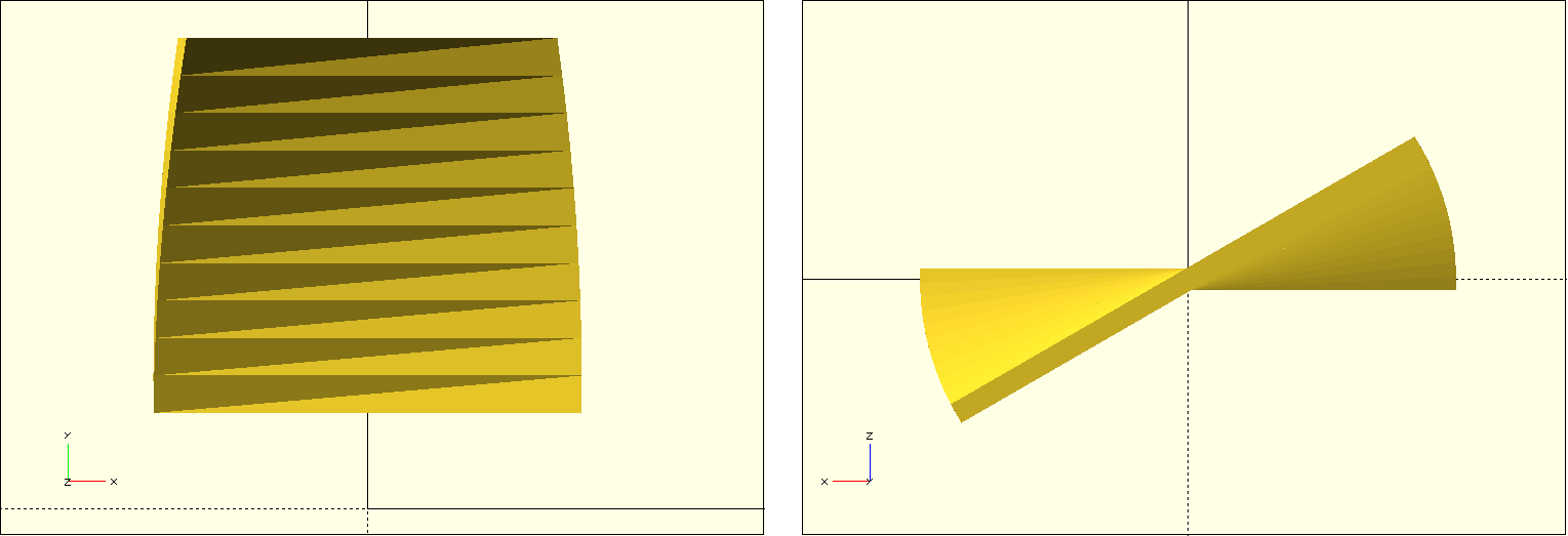
We model the blade itself using the 2D basic shape square and a linear extrusion. We use the twist parameter of linear_extrude to rotate the basic shape during extrusion (Figure 12.). The parameter slices can be used to set how many subdivisions linear_extrude should make along the extrusion to model the twist. The parameter convexity is an auxiliary parameter that ensures that the preview of the geometry is calculated cleanly and has no holes. By default, this parameter has a value of 1. If you find errors in the geometry during preview, it is worth trying to increase this parameter. A value of 10 should be sufficient in practically all cases.
Now we will describe the tapered shape of the fan blade using a Boolean difference operation:
module fan_wheel(
    /* ... */
){

    module blade() {

        /* ... */

        angle =
            atan(
                  ( ( outer_width / 2 * cos( abs( twist ) ) ) -
                    ( inner_width / 2 )
                  ) / blade_height
            );

        height = sin( abs( twist ) ) * outer_width / 2 +
                 thickness;

        width = outer_width / 2 - inner_width / 2;

        depth  =
            sqrt(
                pow( ( outer_width / 2 * cos( abs( twist ) ) ) -
                     ( inner_width / 2 ), 2 ) +
                pow( blade_height, 2 )
            ) + thickness;

        difference(){
            translate( [0, inner_height, 0] )
            rotate( [-90, 0, 0] )
            linear_extrude(
                height    = blade_height,
                twist     = twist,
                slices    = 10 ,
                convexity = 10
            )
            square( [outer_width, thickness], center = true );

            for (i = [0 : 1])
            mirror( [i, 0, 0] )
            translate([
                inner_width / 2,
                inner_height,
                -height
            ])
            rotate( [0, 0, -angle] )
            translate( [0, -depth / 2, 0] )
            cube( [width * 2, depth * 1.5, 2 * height] );

        }

    }

    blade(); // debug
}
/* ... */
We first calculate the angle of the side via the arc tangent function atan. It gets as parameter the difference between inner_width and the outer_width rotated by twist. We use the absolute value (abs) of twist in this case to get the same result even with a negative twist parameter. Afterwards we determine the minimal height, width and depth of the box (cube) that we want to subtract from the fan blade.
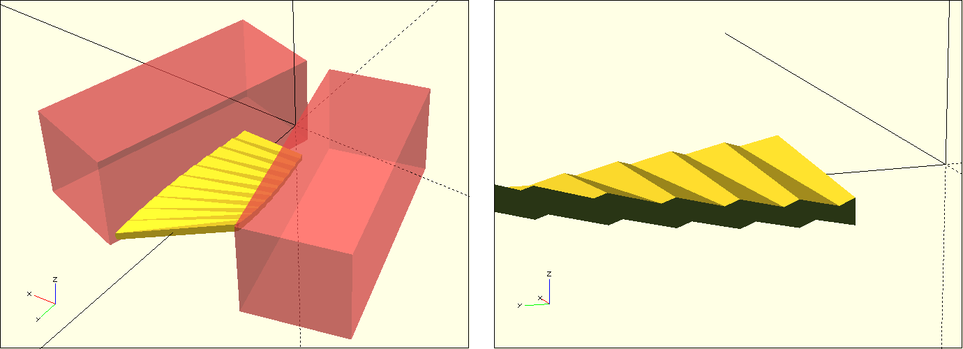
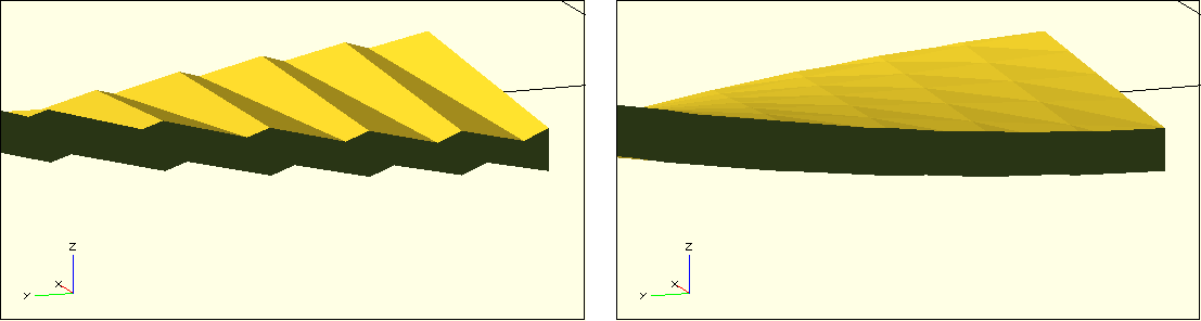
After these preparations, we can now move our fan blade description into the geometry set of a Boolean difference operation and define two boxes that we subtract from the fan blade. Since the sides are mirror symmetric, we can create the two boxes using a combination of for-loop and mirror transformation. We make the box that will be subtracted slightly larger than generally necessary. This way, we also cover situations that may arise due to an “extreme” parameterization of the fan wheel (for example, when the outer_width is very small). Figure 12. shows the position of the described boxes. It also shows that now the sides of our fan blade have become jagged. This jagged structure comes from the fact that the basic 2D shape of our blade is a very thin rectangle, which is internally formed by only two triangles. These are now no longer sufficient to cleanly describe the slanted side edges of the fan blade.
We can fix this problem by using a polygon as 2D base shape instead of a simple rectangle. We need to design the polygon in such a way that it has enough internal “resolution”. To do this, we need to use a little trick:
module fan_wheel(
/* ... */
){
module blade() {
/* ... */
blade_divisions = 10;
difference() {
translate( [0, inner_height, 0] )
rotate( [-90, 0, 0] )
linear_extrude(
height = blade_height,
twist = twist,
slices = 10 ,
convexity = 10
)
translate([
-outer_width / 2,
-thickness / 2
])
polygon( concat(
[for (i = [0 : blade_divisions])
[i * outer_width / blade_divisions, (i % 2) * 0.0001]
],
[for (i = [blade_divisions : -1 : 0])
[i * outer_width / blade_divisions,
thickness + (i % 2) * 0.0001]
]
));
/* ... */
} // difference
}
blade(); // debug
}
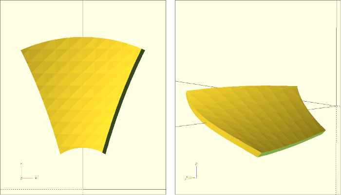
/* ... */We create the polygon from two concatenated (concat) arrays. The first array describes the points of the polygon in X-direction at height 0. The second array describes the points of the polygon in opposite X-direction at height thickness. If all our points in forward and backward direction exactly lie on a line, then OpenSCAD will optimize these points away. To prevent this from happening, we need to move every other point minimally in the Y-direction. We use the modulo operation for this purpose. The expression ‘i % 2’ alternates between 0 and 1 for consecutive i. Our Y-coordinate therefore jumps back and forth from point to point between 0 and 0.0001. By doing this, we prevent OpenSCAD from optimizing and achieve the desired goal of a higher geometric resolution of our 2D base shape. Figure 12. shows how this eliminates the jagged sides of the fan blade.
Our fan blade is now almost finished. We only have to rotate it by its angle_of_attack and add the outer and inner radius to the geometry description. For the outer radius we can do this with a Boolean intersection and for the inner radius we can use another Boolean difference:
module fan_wheel(
    /* ... */
){

    module blade() {

        /* ... */

        difference(){

            intersection(){

                rotate( [0, -angle_of_attack, 0] )
                difference() {

                    /* ... */

                }

                // outer radius
                translate( [0, 0, -height] )
                cylinder(
                    r = outer_radius,
                    h = 2 * height,
                    $fn = 100
                );

            }

            // inner radius
            translate( [0, 0, -height] )
            cylinder( r = inner_radius, h = 2 * height, $fn = 50);

        }

    }

    blade(); // debug
}
/* ... */
We apply the intersection and difference operation only after the rotation by angle_of_attack so that the outer and inner edges of the fan blade remain vertical regardless of the rotation. This completely describes our submodule blade (Figure 12.).
The completion of the main module is now relatively straightforward:
module fan_wheel(
    /* ... */
){

    module blade() {

    }

    // hub
    hub_height =
        sin( abs( angle_of_attack ) ) * inner_width / 2 +
        thickness;

    translate( [0, 0, -hub_height] )
    cylinder( r = inner_radius, h = hub_height * 2, $fn = 50);

    // blades
    for(i = [0 : 360 / blade_count : 359])
    rotate( [0, 0, i] )
    blade();

}
/* ... */
We first determine the height of our hub (hub_height) depending on the angle of attack, the inner width and the material thickness. Then we create the hub as a simple cylinder and center this cylinder along the Z-axis. We now describe the blades using a for-loop, where the step size of the loop variable i results from the parameterized number of blades (360 / blade_count). We use the loop variable i to distribute our submodule blade with an appropriate number of copies over 360 degrees by means of rotation around the Z axis (rotate( [0, 0, i] )).
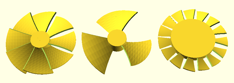
With this our fan wheel is finished (Figure 12.)!
The blades of the fan wheel have a strong overhang, especially towards the outside. Here it is recommended to print with a low layer height and a larger line width. If your 3D printer has a 0.4mm print nozzle, you can print lines with a width of 0.5mm to 0.6mm without problems. As layer thickness you can go down to 0.075mm with most printers. Another trick is to slow down the print speed for the outer walls of the print. This allows the filament to cool down more as it is exposed to the print head blower for longer.
If you print the fan wheel with support structures, you should activate the option for forming a support roof. This will make the interface between the support structure and the 3D model cleaner. An alternative to using support structures is to split the fan wheel into an upper and a lower half using a Boolean intersection:
// upper half
intersection() {
    fan_wheel();

    translate([-100,-100,0])
    cube([200,200,100]);
}

// lower half
translate([120,0,0])
rotate([180,0,0])
intersection() {
    fan_wheel();

    translate([-100,-100,-100])
    cube([200,200,100]);
}
After printing both halves, they can then be glued together. This can be done, for example, with superglue and activator, or with a two-component adhesive. To ensure a clean alignment of the two halves, it can be helpful to drill two holes in the hub using a Boolean difference operation and to insert two pins in these holes and use them as alignment aids when gluing.